
Device for packaging and application of a product

a technology for packaging and products, applied in the direction of brushes, packaging goods, applications, etc., can solve the problems of high degree of precision, high cost, and relative difficulty in ensuring the leakage-tight bearing of the rod or the grasping element,

Inactive Publication Date: 2008-11-18
LOREAL SA
View PDF14 Cites 7 Cited by
  • Summary
  • Abstract
  • Description
  • Claims
  • Application Information

AI Technical Summary

Benefits of technology

[0008]It is an object of the invention to provide a packaging and applicator device which avoids or reduces at least some and preferably all of the disadvantages of the prior art.
[0010]A further object of the invention is to provide a device that is simple to manufacture on an industrial scale.
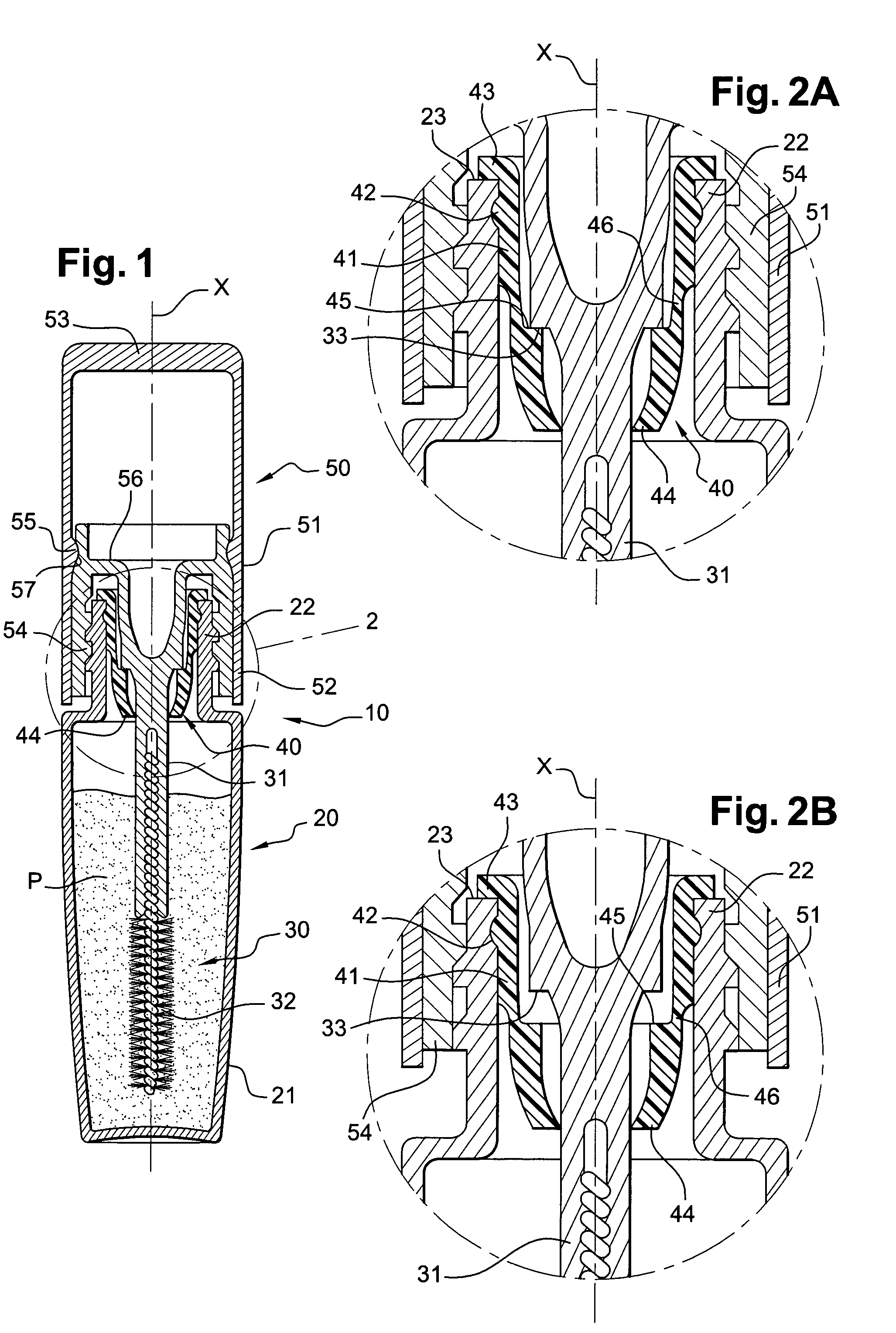
[0012]When the closure element is in the closed position on the container, the zone of greater deformability can for example stretch by 50% of its length, measured along the axis of the rod. The zone of greater deformability of the wiper element enables the sealing zone on which the seal is made to be axially displaced, thereby imparting a wider degree of tolerance to the device. Development and production conditions can thus be facilitated, thereby facilitating industrial-scale manufacture of the device.
[0013]According to one preferred example, the wiper element can include a wiping zone formed at a distance from the sealing zone. In particular, by way of example, the sealing zone can be located at a sufficient distance from the wiping zone or wiper portion so that the wiping zone is not deformed when the rod is in leaktight contact against the sealing zone. In addition, the wiping function and the sealing function of the wiper element can thus be separated from each other.
[0014]The sealing zone can be formed at a distance from the upper end of the wiper element. As the rod comes into leaktight contact against a small surface formed at a distance from the upper end of the wiper element, the product remaining on the wiper element is not driven towards the outside of the container, and fouling of the outside of the container can thereby be avoided or reduced.
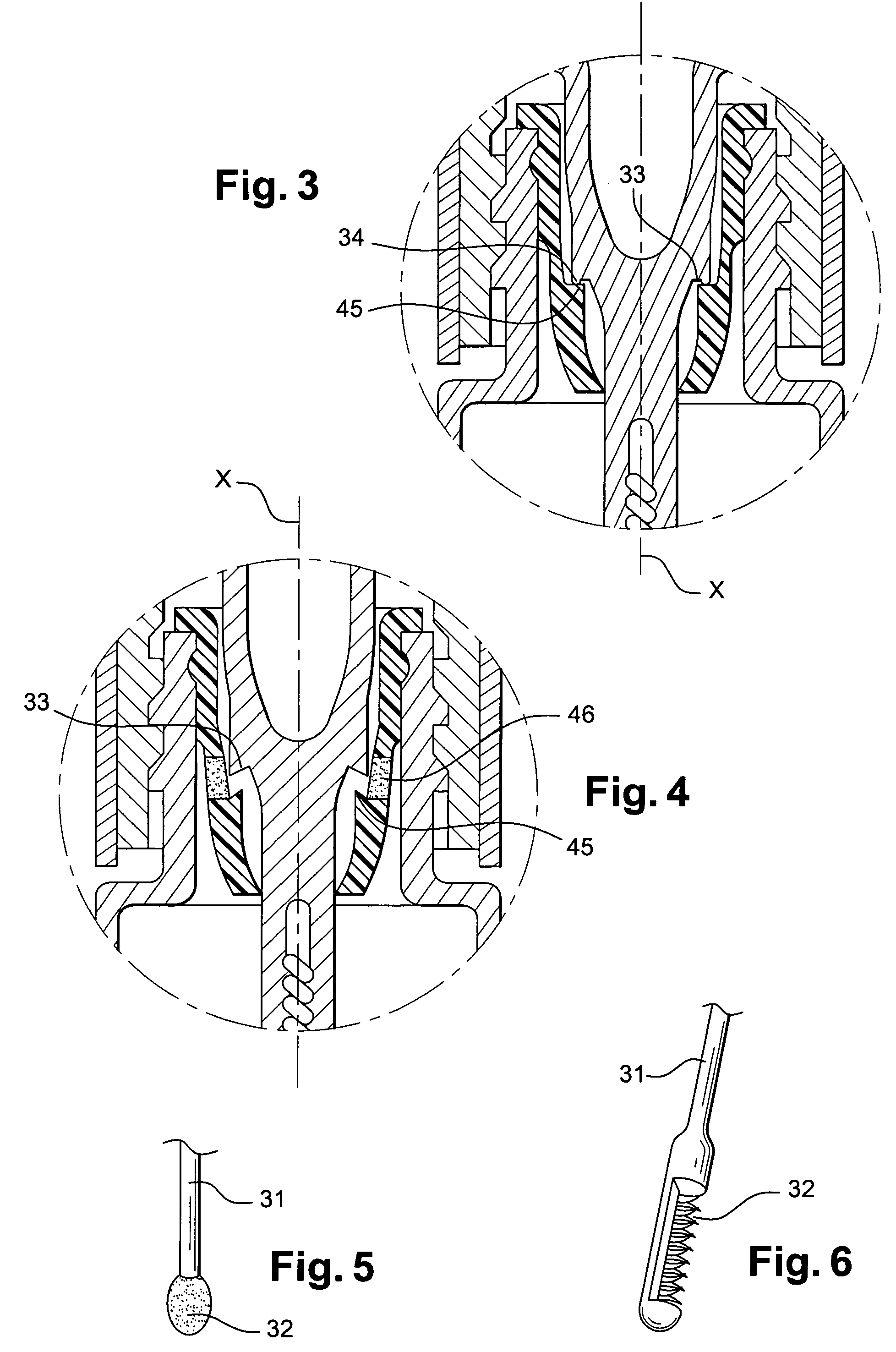
[0017]Also by way of example, the sealing zone of the wiper element can be delineated by a shoulder. The shoulder can extend radially towards the inside of the wiper element, delineating an annular surface perpendicular to the axis X of the rod. As a variant, the shoulder can delineate a conical surface converging towards the opening of the container. Such a shape serves to compensate any deformation of the shoulder of the wiper element when the rod exerts a force directed towards the lower end of the wiper element.

Problems solved by technology

Given the manufacturing tolerances of the device, it is relatively difficult to ensure that the portion of the rod or grasping element bears in a leaktight manner against the wiper element exactly at the end of the screwing action of the cap, particularly when the seal is conical.
It is in effect difficult to fit the two cones so that contact is not made too early, thereby precluding completion of the screwing action, or too late in which case there is no contact between the rod and the wiper element and therefore no seal is made.
Mass production of such devices therefore calls for a high degree of precision which generates relatively high costs.
After several successive uses, this deposit of product extends beyond the upper end of the wiper element, eventually fouling the screw thread on the neck of the container.
It then becomes difficult or even impossible to screw the cap onto the neck of the container, thereby preventing closure of the container.

Method used


Image

  • Device for packaging and application of a product
  • Device for packaging and application of a product
  • Device for packaging and application of a product

Examples


Embodiment Construction

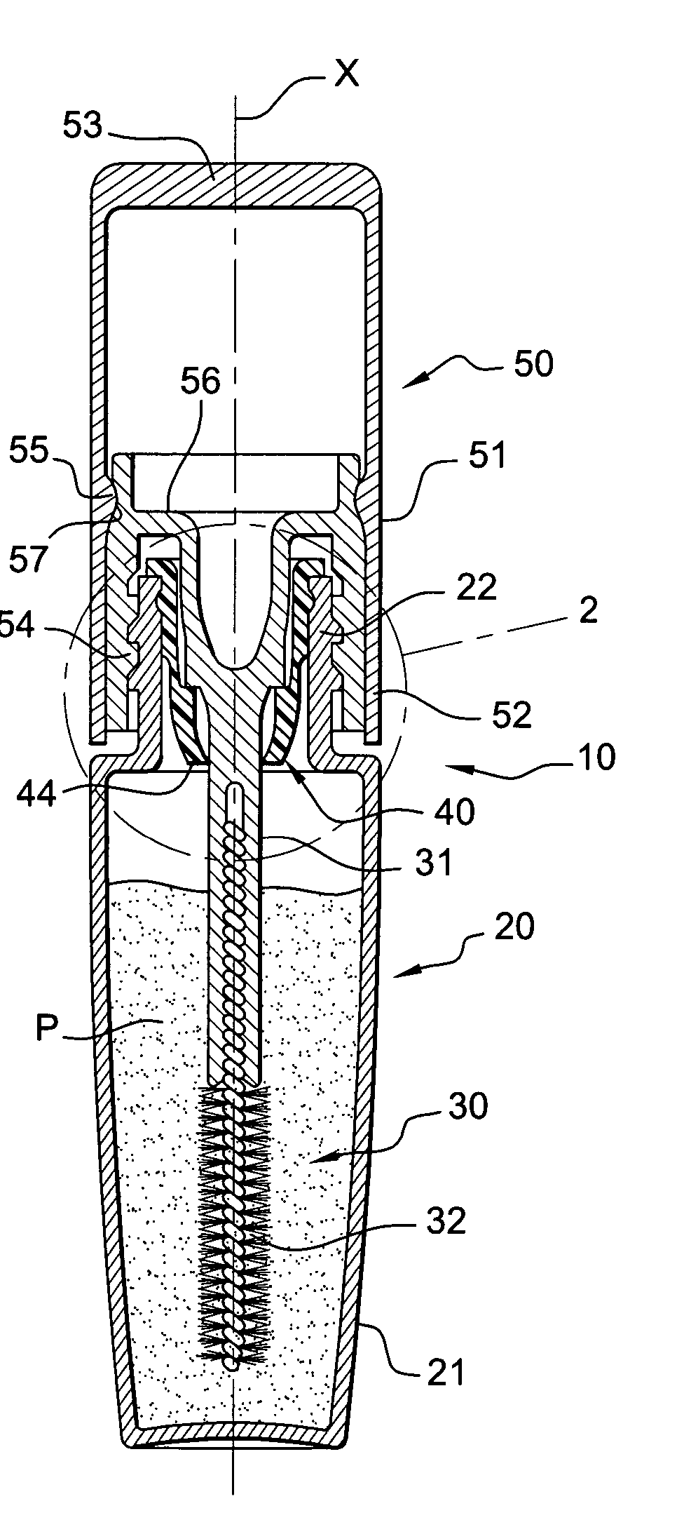
[0028]FIG. 1 depicts a device 10 for packaging and applying a product P, for example a cosmetic product such as mascara.

[0029]This device 10 includes a container 20, for example of elongated shape, an applicator 30 and a wiper element 40 permanently fixed on the container 20.

[0030]The container 20 includes a body 21 containing the product fitted, in the upper part in the example considered, with a neck 22. The neck 22 is threaded externally in the example illustrated. The upper end of the neck defines an opening in which the wiper element 40 is engaged in this example.

[0031]The applicator 30 includes a rod 31 having an axis X, of circular cross-section over substantially its full length in the example considered. The applicator 30 is fitted at its lower end with an applicator element 32 in the form of a twisted-core brush in the example illustrated.

[0032]The rod 31 is connected at its upper end to a grasping element 50 which can also provide a closure element for the container 20.

[0...


PUM


Abstract

A device for packaging and applying a product includes a container to hold the product, with this container having an opening at its upper end, a wiper element engaged at least partially in the opening, an applicator including an applicator element carried by a rod of axis X, and a closure element for the container. The wiper element includes a sealing zone against which part of the rod is capable of coming into leaktight contact when the closure element is in the closed position, and a zone of greater deformability, located above the sealing zone, and which is capable of stretching axially when the rod is bearing against the sealing zone of the wiper element.

Description

CROSS-REFERENCE TO RELATED APPLICATIONS[0001]This document claims priority to French Application Number 04 51462, filed Jul. 6, 2004 and U.S. Provisional Application No. 60 / 587,490, filed Jul. 14, 2004, the entire content of which are hereby incorporated by reference.FIELD OF THE INVENTION[0002]The present invention relates to devices for packaging and applying a product. The invention can be particularly advantageous for packaging and applying cosmetic products, for example a mascara, a nail varnish or a liquid lip color.[0003]The invention relates more particularly to a device including a container holding a product, an applicator incorporating an applicator element, a grasping element, a rod connecting the applicator element to the grasping element, and a wiper element arranged to at least partially wipe the applicator element when it is withdrawn from the container. The grasping element can additionally be in the form of a cap to ensure the closure of the device, for example, by...

Claims


Application Information

Patent Timeline
Patent Type & Authority Patents(United States)
IPC IPC(8): A46B11/00A46B17/08
CPCA45D40/267A46B9/021
Inventor ROUSSELET, GUILHEM
Owner LOREAL SA
Learn More