Blade with shroud

a turbine and shroud technology, applied in the direction of liquid fuel engines, vessel construction, marine propulsion, etc., can solve the problems of bending torques of different bending torques, symmetrical balance of shroud elements, and greater bending torques

Active Publication Date: 2007-10-04
ANSALDO ENERGIA SWITZERLAND AG
View PDF8 Cites 7 Cited by
  • Summary
  • Abstract
  • Description
  • Claims
  • Application Information

AI Technical Summary

Benefits of technology

[0009] An object of the invention is to provide a blade and blade arrangement of the type mentioned initially, by means of which one or more disadvantages of the prior art are reduced or avoided.

Problems solved by technology

Since, however, modern blade sections are generally designed to be twisted and also curved in some cases, this means that the shroud elements are not symmetrically balanced.
This nonuniformity of the platform sections leads to bending torques of different magnitude on the pressure-side and suction-side platform sections when the blade is used in a rotor, owing to the centrifugal forces acting on the platform sections.
The pressure-side platform section in FIG. 2c has a larger projection length than the suction-side platform section, and is subject to a greater bending torque during rotation, because of the higher mass and the longer lever arm, and this in turn leads to greater elastic deformation of the pressure-side platform section.
In addition to the high bending forces, the shrouds, particularly for turbine stages, are often additionally subject to very high temperatures from the main flow.
The combined load has a negative influence on the time / creepage behavior of the platform sections.
Those platform sections which have a longer free projection length and in consequence are subject to a greater bending torque during operation are also deformed by an increased creepage behavior.
Particularly in the turbine area, the fluid in the main flow is in this case at a very high temperature, resulting in a dramatic rise in the material temperature both on the rear face of the shroud and on the adjacent components.
On the one hand, this once again leads to an increase in the creepage behavior described above, and on the other hand leads to an increased temperature load on the adjacent components.
In any case, this effect leads in some cases to a very considerable shortening of the life of virtually all of the components which are affected.

Method used


Image

  • Blade with shroud
  • Blade with shroud
  • Blade with shroud

Examples


Embodiment Construction

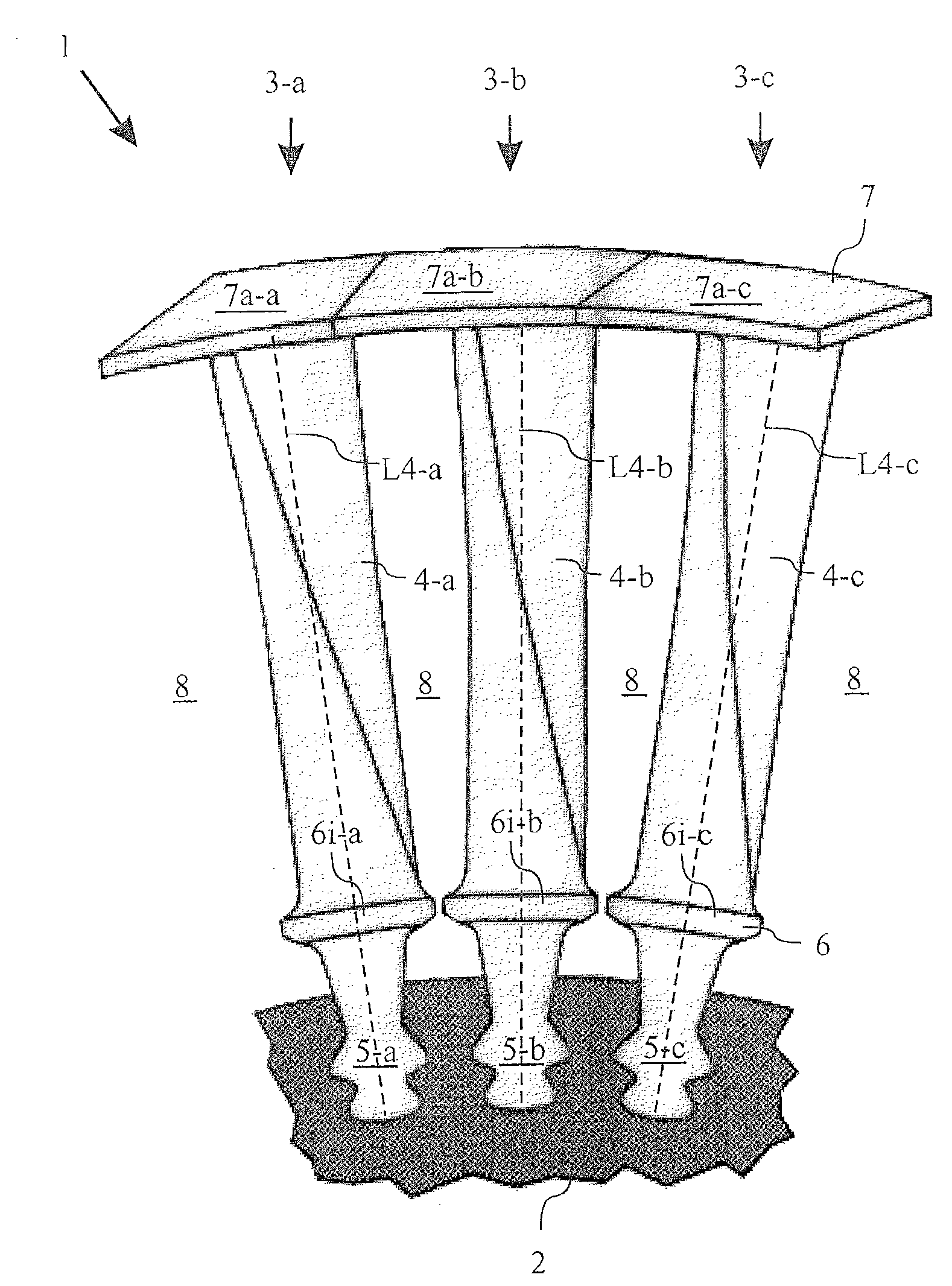
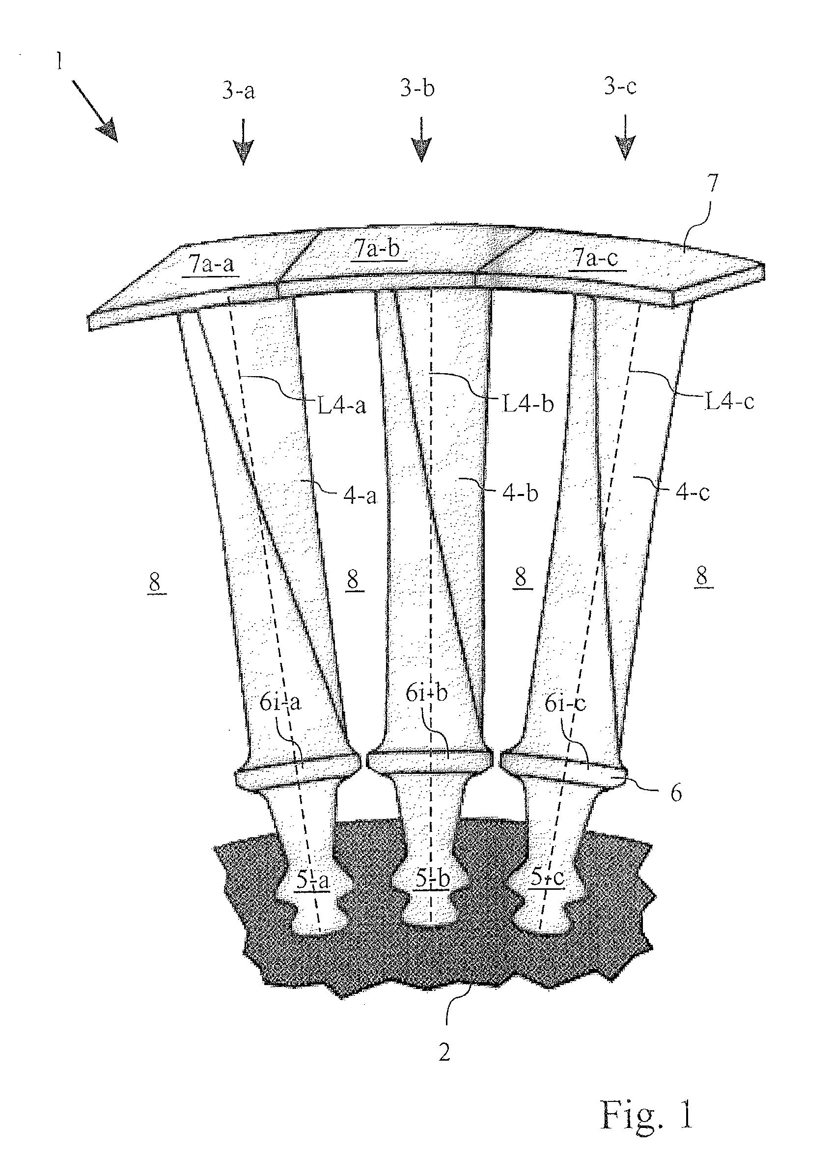
[0045]FIG. 1 shows a schematic illustration of detail of a rotor 1 as known from the prior art, which is designed in a manner known per se with an inner shroud 6 and an outer shroud 7. The rotor 1 illustrated in FIG. 1 is in this case in the form of a rotor for a turbine.

[0046] The rotor 1 illustrated in FIG. 1 has a centrally arranged rotor shaft 2 and a plurality of blades 3-a, 3-b and 3-c arranged alongside one another on the circumference of the rotor shaft 2. The blades 3-a, 3-b, 3-c each have a blade section 4-a, 4-b and 4-c, respectively, and are anchored via firtree roots 5-a, 5-b and 5-c in the rotor shaft 2. A respective inner shroud element 6i-a, 6i-b and 6i-c is arranged between the respective firtree root 5-a, 5-b and 5-c and the blade section 4-a, 4-b and 4-c of each blade. The inner shroud elements 6i-a, 6i-b and 6i-c are each in the form of platforms and extend essentially at right angles to the respective blade section longitudinal direction L4-a, L4-b or L4-c. Fur...


PUM


Abstract

A blade for a turbo machine has a blade section and a shroud element terminating the blade section in the blade section longitudinal direction. The blade section has a suction face and a pressure face. The shroud element extends essentially at right angles to the blade section longitudinal direction and has a first platform section projecting beyond the blade section and a second platform section projecting beyond the blade section. The platform sections are asymmetric with respect to one another. At least the first platform section of the shroud element is arranged at an additional inclination angle with respect to a normal alignment of the first platform section, with the additional inclination angle being in the opposite direction to the bending torque which acts on the first platform section during operation.

Description

[0001] This application is a continuation of International Patent Application PCT / EP2005 / 054327, filed on Sep. 2, 2005 and claims priority to Swiss Patent Application CH 01483 / 04, filed on Sep. 8, 2004. The entire disclosure of both applications is incorporated by reference herein. [0002] The present invention relates to a blade for a turbomachine equipped with a shroud, and to a blade arrangement having a plurality of blades, which are arranged on the circumference of a turbomachine in a row with respect to one another.BACKGROUND [0003] It is known per se from the prior art for blade rows of turbines to be equipped with shrouds. The shrouds may in this case, for example, be in the form of outer shrouds on the outer circumference of a blade row. The shrouds are also generally in the form of split shrouds, with the relevant shroud being subdivided on the circumference of a blade row into a large number of shroud elements corresponding to the number of blades in the blade row. Each bl...

Claims


Application Information

Patent Timeline
Patent Type & Authority Applications(United States)
IPC IPC(8): F01D5/22
CPCF01D5/225
Inventor BOEGLI, ANDREASRITCHIE, JAMES
Owner ANSALDO ENERGIA SWITZERLAND AG
Why Eureka
Try Eureka