System and method for optical measurement of a target at multiple positions

a target and optical measurement technology, applied in the field of system and a method for optical measurement of a target at multiple positions, can solve the problems of high cost of image detectors which qualify for accurate optical measurements, long measurement time, and inability to meet the requirements of a large number of samples, so as to avoid or reduce the disadvantages of the prior, efficient and cost-effective

Active Publication Date: 2014-03-13
TEKNOLOGIAN TUTKIMUSKESKUS VTT
View PDF9 Cites 8 Cited by
  • Summary
  • Abstract
  • Description
  • Claims
  • Application Information

AI Technical Summary

Benefits of technology

[0005]The purpose of the present invention is to avoid or reduce disadvantages of the prior art. The objective of the invention is therefore to provide an optical measurement system for optical measurement of one or several targets at multiple positions in an efficient and cost-effective manner.
[0007]The inventive measurement system allows measuring one target position with one detector element, and the number of required detector elements is thus small. Suitable line detectors, for example, are inexpensive to manufacture, and they are available for measurements with long radiation wavelengths such as NIR.
[0008]When a controllable Fabry-Perot interferometer is used as a filter, it is possible to select the measurement wavelength as required. The Fabry-Perot interferometer can be used for filtering the radiation received from the target, whereby the Fabry-Perot interferometer is located between the light guide and the detector, or the Fabry-Perot interferometer can also be used for filtering radiation of a radiation source. It is also possible to use two Fabry-Perot interferometers which allow the selection of the illumination or measurement wavelength in a larger wavelength range than with a single Fabry-Perot interferometer.
[0019]Significant advantages can be achieved with the invention when compared to the known solutions. It is possible to achieve simultaneous measurements from multiple positions of a target, and it is possible to measure more than one wavelength component simultaneously. It is therefore possible to achieve efficient multipoint measurement. However, the inventive solution can be implemented with low-cost detectors, such as row detectors. No individual detectors are needed as the measurement beams can be detected with a single row detector which has several detector elements in line. The inventive measurement system can also be used for measuring radiation of long wavelengths such as NIR as suitable row detectors are available. A common slit, common Fabry-Perot interferometer and common row detector can be used for all fibres of the measurement radiation. Individual lenses for each fibre or each detector are not necessarily needed between the fibres and the detector elements as the radiation may be directly coupled between the fibre ends and the Fabry-Perot interferometer and between the Fabry-Perot interferometer and detector elements. This way the system can be made small in size, and the production is simple and can be automated. Low production cost can thus be achieved.

Problems solved by technology

When such measurements are made successively the measurement tends to take a long time.
This way, however, providing the measurements for a large number of samples takes a long time.
However, such image detectors which qualify for accurate optical measurements are expensive.

Method used


Image

  • System and method for optical measurement of a target at multiple positions
  • System and method for optical measurement of a target at multiple positions

Examples


Embodiment Construction

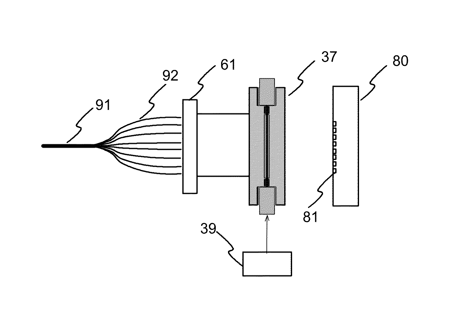
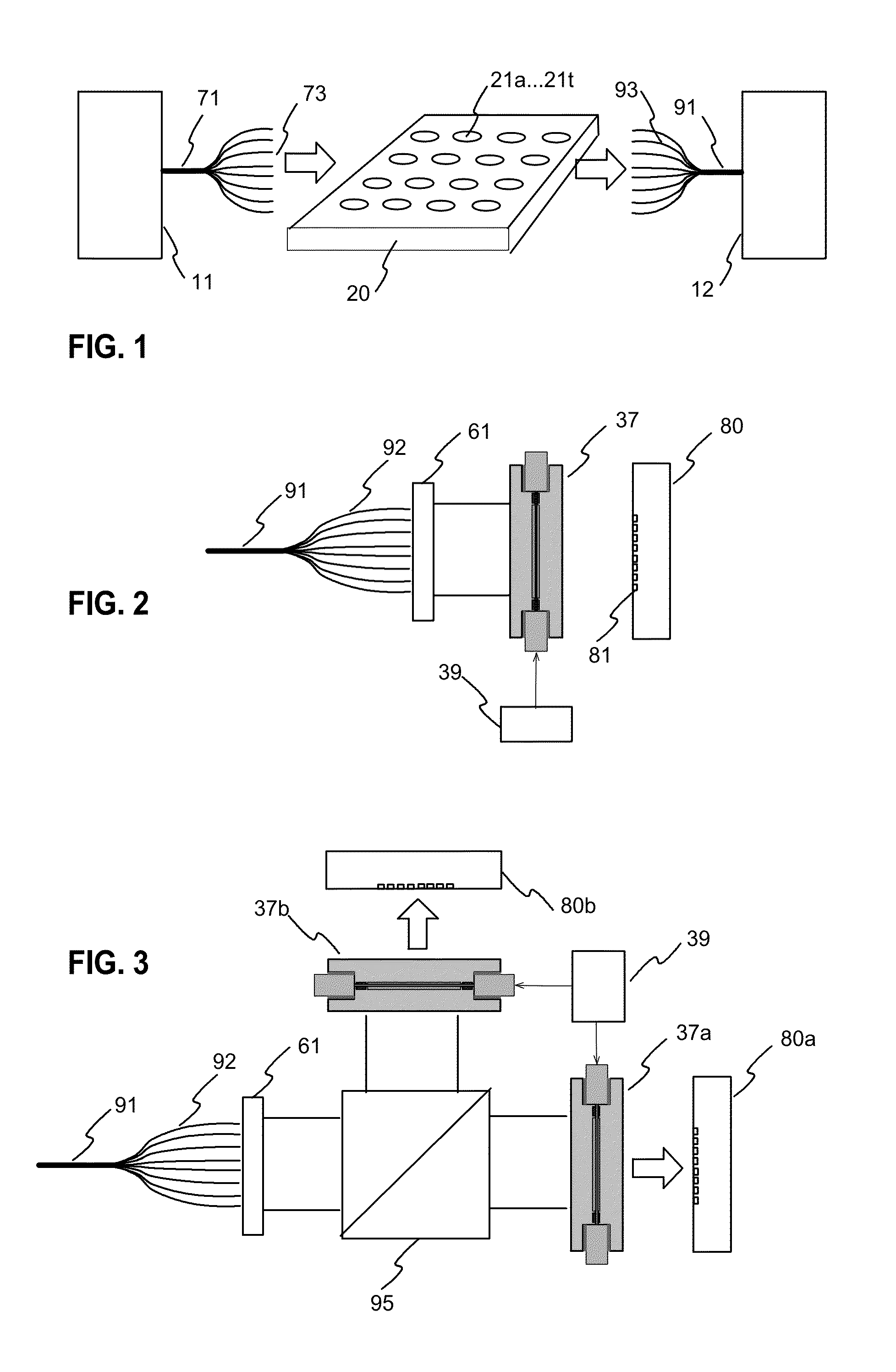
[0027]FIGS. 1 illustrates a general block diagram for an embodiment of the measurement system according to the invention. The system has an illuminating part 11 for providing illumination for the target. The illuminating part has a suitable radiation source, and the radiation is directed to the first ends of the illuminating optical fibres of the optical fibre bundle 71. The second ends of the optical fibres are positioned close to the measurement target 20 so that the end of each optical fibre is close to a determined measurement position 21a . . . 21t of the target. The target of FIG. 1 has 20 measurement positions, such as samples, and thus the optical fibre bundle has 20 optical fibres for illuminating each target position. However, it is also possible that two or more optical fibres are used to guide illumination to each target position.

[0028]The measurement system also has a bundle of optical fibres for receiving radiation from the sample positions. The first ends 93 of the op...


PUM


Abstract

The invention relates to a system and a method for optical measurement of a target, wherein the target is illuminated, either actively illuminated, reflecting ambient light, or self illuminating, and a measurement radiation beam received from the target or through it is detected. The measurement system has optical fibres for guiding radiation from / to target positions. Radiation of several target positions is simultaneously filtered by a Fabry-Perot interferometer and detected by a row detector, for example.

Description

TECHNICAL FIELD[0001]The invention relates to a system and a method for optical measurement of a target at multiple positions, wherein the target is either actively illuminated, reflecting ambient light, or self illuminating, and a measurement light beam received from the target or through the target is detected.BACKGROUND TECHNOLOGY[0002]Optical measurement systems are used for e.g. analysing properties or material contents of a target. Such optical measurement systems typically measure absorbance, reflection or emission of a target. The measurement systems usually have filters in order to facilitate the measurements with specified radiation wavelengths. Such filters can be controllable Fabry-Perot interferometers, for example.[0003]It is often necessary to provide measurements of a target with two or more wavelengths. When such measurements are made successively the measurement tends to take a long time. Document Fl119830B1 discloses a system for optical measurement where radiatio...

Claims


Application Information

Patent Timeline
Patent Type & Authority Applications(United States)
IPC IPC(8): G01J3/51
CPCG01J3/51G01J3/0294G01J3/10G01J3/26G01J3/2803G01J3/32G01J3/36G01J3/0218
Inventor JUUTI, MIKKOSAARI, HEIKKIKERANEN, HEIMOMALINEN, JOUKO
Owner TEKNOLOGIAN TUTKIMUSKESKUS VTT
Why Eureka
Try Eureka