Evaporator for ambient water bodies, and related system and method

a technology of ambient water bodies and evaporators, applied in the field of evaporators, can solve the problems of low evaporation rate, unworkable evaporation rate, limited utility of natural evaporation, etc., and achieve the effect of avoiding the effect of viscous or fluid drag effects of the wall

Inactive Publication Date: 2021-02-18
RESOURCE WEST
View PDF0 Cites 0 Cited by
  • Summary
  • Abstract
  • Description
  • Claims
  • Application Information

AI Technical Summary

Benefits of technology

[0010]The radial positioning of the water injection location within the air flow stream also may vary. A presently-preferred radial location comprises at or on the longitudinal axis, but the location or locations also may be spaced radially from the longitudinal axis, instead of or in addition to one or more longitudinal locations. If the air flow channel is assumed to comprise an air flow exit having a radius R normal to the longitudinal axis, the radially spaced location may be spaced only slightly off the longitudinal axis, i.e., greater than 0% and at radial locations extending to just before the interior wall of the air flow channel, just less that radius R. Preferably the radial location or locations are sufficiently far from the air flow channel wall the viscous or fluid drag effects associated with the wall are avoided. Although this boundary or zone will vary from application to application, preferably the radial location or locations will be between the longitudinal axis and about 75% of the radius R relative to the longitudinal axis.

Problems solved by technology

These ponds often contain high levels of dissolved solids or ions, possibly various forms of hydrocarbons, and other components that could be undesirable or deleterious to the environment if released.
Natural evaporation is of limited utility because the evaporation rate usually is unworkably slow.
Although this approach has met with substantial success, it is limited in some applications in that it can result in relatively low evaporation rates and relatively low evaporation efficiencies.
It also can yield relatively limited water and air mixing.

Method used


Image

  • Evaporator for ambient water bodies, and related system and method
  • Evaporator for ambient water bodies, and related system and method
  • Evaporator for ambient water bodies, and related system and method

Examples


Embodiment Construction

[0075]Reference will now be made in detail to the presently-preferred embodiments and methods of the invention as illustrated in the accompanying drawings, in which like reference characters designate like or corresponding parts throughout the drawings. It should be noted, however, that the invention in its broader aspects is not limited to the specific details, representative devices and methods and illustrative examples shown and described in this section in connection with the preferred embodiments and methods. The invention according to its various aspects is particularly pointed out and distinctly claimed in the attached claims read in view of this specification, and appropriate equivalents.

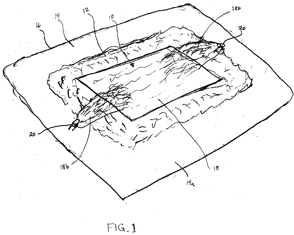
[0076]Evaporators according to the various aspects and embodiments of the invention are useful for evaporating water from ambient water bodies, for example, such as ponds, lakes, reservoirs, rivers, tanks, impoundment ponds, flooded areas, and the like, as noted above. To provide an illustra...


PUM

PropertyMeasurementUnit
angleaaaaaaaaaa
distanceaaaaaaaaaa
lengthaaaaaaaaaa

Abstract

An evaporator is provided for evaporating water from an ambient water body. The evaporator includes a housing that in turn includes an air flow channel and an air flow exit. The evaporator also includes an air flow induction device, such as a fan or impeller, that facilitates the directing of an air flow stream through the air flow channel and out the air flow exit. A water injection device is in fluid communication with the air flow channel and is disposed to inject the water from the water body into the air flow stream at a water injection location within the air flow stream and proximate to the air flow exit. A water injection system for injecting water from an ambient water body into an air flow stream directed by an air flow channel of an evaporator also is disclosed, wherein the air flow channel is disposed about a longitudinal axis. The water injection system includes an elongated tubular member disposed parallel with respect to the longitudinal axis, a plurality of water injection nodes disposed at the tubular member and spaced from one another longitudinally, and a support for positioning the elongated tubular member within or proximate to the air flow channel so that the plurality of water injection nodes are positioned within the air flow stream.

Description

CROSS-REFERENCES TO RELATED APPLICATIONS[0001]This application claims priority and the benefit of earlier filing date to U.S. Provisional Application No. 62 / 656,856, No. 62 / 656,887, and No. 62 / 656,906, all of which were filed on Apr. 12, 2018. The entire contents of each of these patent applications are hereby expressly incorporated herein by reference in their entirety as if fully set forth herein, including without limitation the specification or disclosure, claims, abstract, and all drawings, figures and tables thereof.FIELD OF THE INVENTION[0002]The present invention relates to evaporators and related components, systems and methods for evaporating water from an ambient body of water, for example, such a pond, lake or the like. This includes artificial water bodies, for example, as are commonly used in industrial applications such as oil and gas exploration, mining, waste water management, and the like.BACKGROUND OF THE INVENTION AND RELATED ART[0003]There are many applications ...

Claims


Application Information

Patent Timeline
Patent Type & Authority Applications(United States)
IPC IPC(8): B01D1/20B01D1/00C02F1/12C02F1/04
CPCB01D1/20B01D1/007C02F2103/007C02F1/048C02F1/12F04D25/08F04D29/34F04D29/32F04D29/54F04D29/52F04D29/705F04D29/601F04D13/066F04D29/384Y02W10/37C02F2103/10C02F2103/32B01D1/0005B01D1/0094F05B2240/301
Inventor BALLANTYNE, ROBERTMACDONALD, WILLIAM
Owner RESOURCE WEST
Why Eureka
Try Eureka