Rotorcraft having lighting equipment with a plurality of headlights operated for landing, winching, and searching

a technology of rotorcraft and headlights, which is applied in the field of rotorcraft equipment, can solve the problems of limited freedom in selecting locations on the rotorcraft, affecting the operation of landing, winching, and large frame and/or support, and reducing the cost of obtaining lighting equipment. , the effect of reducing the cost of obtaining lighting equipmen

Inactive Publication Date: 2014-09-16
EUROCOPTER
View PDF14 Cites 14 Cited by
  • Summary
  • Abstract
  • Description
  • Claims
  • Application Information

AI Technical Summary

Benefits of technology

[0042]The headlights included in the lighting equipment with which the rotorcraft is fitted are suitable for being incorporated relatively freely in the outside wall of the rotorcraft, while selectively producing a plurality of lighting functions, in particular the landing lighting function, the searching lighting function, and / or the winching lighting function. Whatever the function selected by an on-board operator, a pilot or copilot in particular, the headlights individually mounted on the rotorcraft at selected locations on its outside wall may be analogous mechanical structures making them easier to install and reducing the cost of obtaining lighting equipment. Incorporating and installing headlights in the outside wall of the rotorcraft leads to a searching light function that is effective, while making use only of headlights of other searching devices that are included in the lighting equipment fitted to the rotorcraft. The number of headlights potentially usable for searchlights by an on-board operator is optimized without leading to redundancy among the headlights that need to be installed on the rotorcraft in order to obtain all of the lighting functions that are available to the operator.
[0043]The drag effects that could be induced by the headlights used for searching lighting function while they are not in use are avoided, without it being necessary to intervene concerning their permanent installation on the rotorcraft. The consequences that arise as a result of possible masks constituting obstacles to the passage of the light beams emitted by the headlights towards the search zone for illuminating are limited. The facility made available by remote installation on the rotorcraft of a plurality of headlights, each of moderate individual power, does not impede convergence of the light beams that the respective headlights emit.
[0064]The main control member is advantageously arranged as a stick hinged to move in multidirectional manner, such as a control stick or lever implantable in the armrest of a seat. Such a stick is easily optionally fitted with at least a said focusing control member, a said lighting sweep control member, a said convergence control member, a said zone control member, and the multiple-choice control member. The stick forming the main control member is suitable for easily receiving the additional control members, which are for example organized as control buttons or the like. Such a button may be arranged as a slider, as a multidirectional hat button, or indeed as a multiple-choice control member. The stick and the optional additional control members with which it may be fitted can be operated comfortably by an operator using one hand.

Problems solved by technology

Given their functions, there is limited freedom in selecting locations on the rotorcraft for the headlights making up lighting devices that are dedicated to landing and / or to winching.
Lighting devices for searching are more complex and bulky than lighting devices dedicated to landing and winching.
The frame and / or the support are potentially large with considerable bulk, e.g. being mounted on a mast, or the like.

Method used


Image

  • Rotorcraft having lighting equipment with a plurality of headlights operated for landing, winching, and searching
  • Rotorcraft having lighting equipment with a plurality of headlights operated for landing, winching, and searching
  • Rotorcraft having lighting equipment with a plurality of headlights operated for landing, winching, and searching

Examples


Embodiment Construction

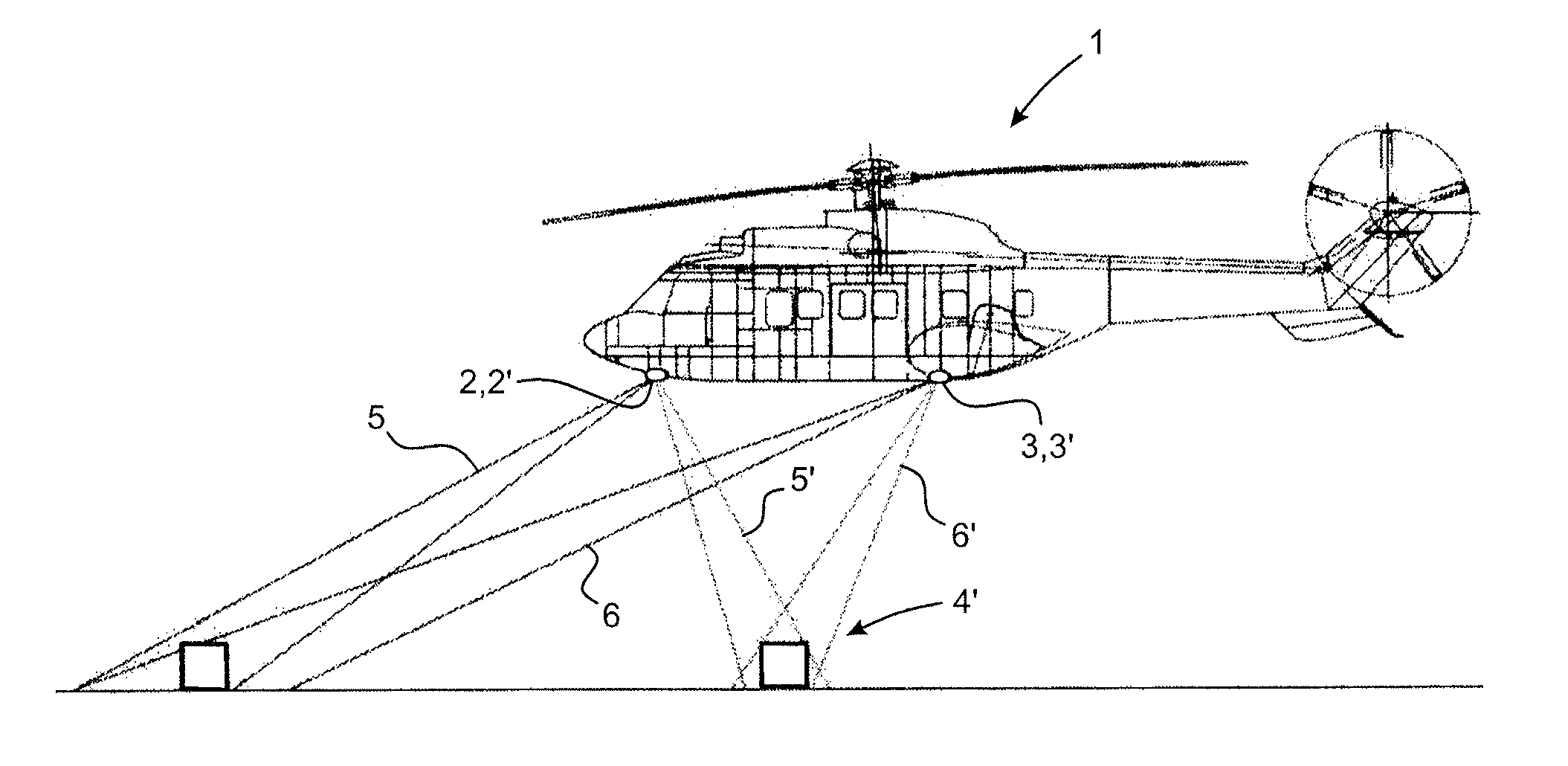
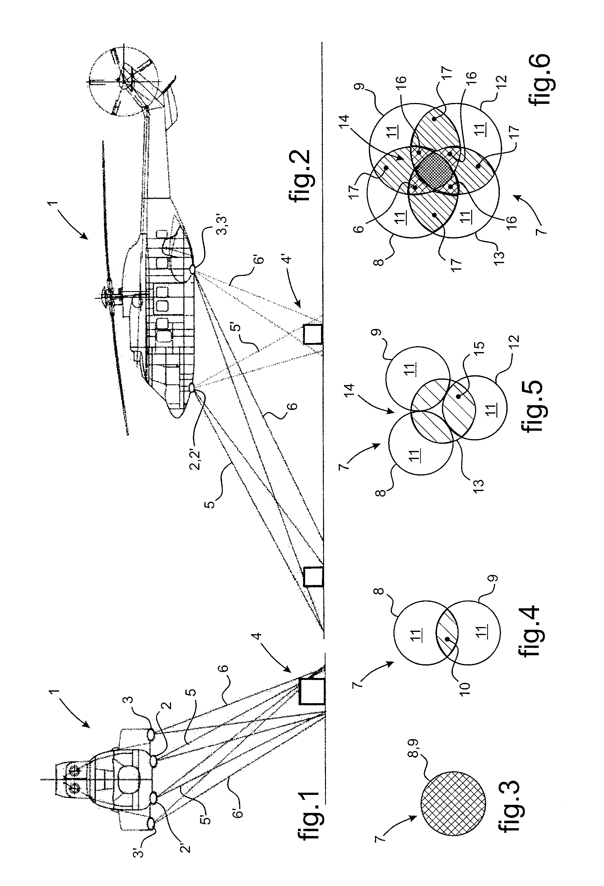
[0089]In FIGS. 1 and 2, a rotorcraft 1 has on-board lighting equipment in order to light the surrounding environment, and more particularly one or more zones that are remote from the rotorcraft. The lighting equipment is organized to produce a plurality of lighting functions, including a landing lighting function, a searching lighting function, and a winching lighting function. All of these lighting functions are obtained by a set of headlights 2, 2′, 3, 3′ included in the lighting equipment, including two landing headlights 2, 2′ for performing the landing lighting function, and winching headlights 3, 3′ for performing the winching lighting function.

[0090]The headlights 2, 2′, 3, 3′ are installed on an outside wall of the rotorcraft 1, being spaced apart from one another, and being four in number in the example rotorcraft shown. Two landing headlights 2, 2′ are spaced apart sideways at the front of the rotorcraft 1, and two winching headlights 3, 3′ are spaced apart at the rear of ...


PUM


Abstract

A rotorcraft (1) having on-board lighting equipment for lighting the surrounding environment. The lighting equipment comprises a plurality of headlights (2, 2′, 3, 3′) that are allocated to respective specific lighting functions in landing and in winching. The headlights (2, 2′, 3, 3′) are also operated to perform a searching lighting function. Control means determine which headlights (2, 2′, 3, 3′) are to be operated depending on a lighting function selected by an operator and depending on where the headlights are located on the rotorcraft (1). A search zone (4, 4′) for illuminating is identified by identification means on the basis of a lighting command common to the headlights (2, 2′, 3, 3′). Coordination means cause the headlights (2, 2′, 3, 3′) to converge on the identified search zone (4, 4′), while taking account of their respective locations on the rotorcraft (1).

Description

CROSS REFERENCE TO RELATED APPLICATIONS[0001]The present application claims priority to French patent application FR 11 02395 filed on Jul. 29, 2011, the content of which is incorporated in its entirety by reference herein.BACKGROUND OF THE INVENTION[0002](1) Field of the Invention[0003]The present invention relates to the field of rotorcraft, and more particularly it relates to equipment on board rotorcraft for lighting the surrounding environment.[0004]The present invention provides a rotorcraft having such equipment, comprising a plurality of devices for lighting respective zones for illumination that are remote from the rotorcraft. The present invention also provides such rotorcraft lighting equipment, and a method of operating it.[0005](2) Description of Related Art[0006]Rotorcraft are fitted with various on-board devices for lighting the surrounding environment. In general terms, such lighting devices make use of one or more headlights, and of means for controlling the emissio...

Claims


Application Information

Patent Timeline
Patent Type & Authority Patents(United States)
IPC IPC(8): G08B21/00B64D47/04
CPCB64D47/04
Inventor FIDANZA, RAPHAEL
Owner EUROCOPTER
Why Eureka
Try Eureka