One Step Surgical Screw Fixation Technique and Design

a screw and screw technology, applied in the field of surgical screws, can solve the problem that the screw has not reached its full potential, and achieve the effect of reducing overhead costs, maximizing cost effective use of screws, and reducing large surgical caddies

Inactive Publication Date: 2021-07-08
EPSTEIN JOSHUA +1
View PDF0 Cites 0 Cited by
  • Summary
  • Abstract
  • Description
  • Claims
  • Application Information

AI Technical Summary

Benefits of technology

[0016]According to one aspect of the invention, the screws are individually prepackaged in various screw sizes, which allows for more cost effective utilization of screws. Additionally, large surgical caddies and overhead costs are minimized. Alternatively, kits of multiple screws are provided.

Problems solved by technology

However, the screw has yet to reach its full potential.

Method used


Image

  • One Step Surgical Screw Fixation Technique and Design
  • One Step Surgical Screw Fixation Technique and Design
  • One Step Surgical Screw Fixation Technique and Design

Examples


Embodiment Construction

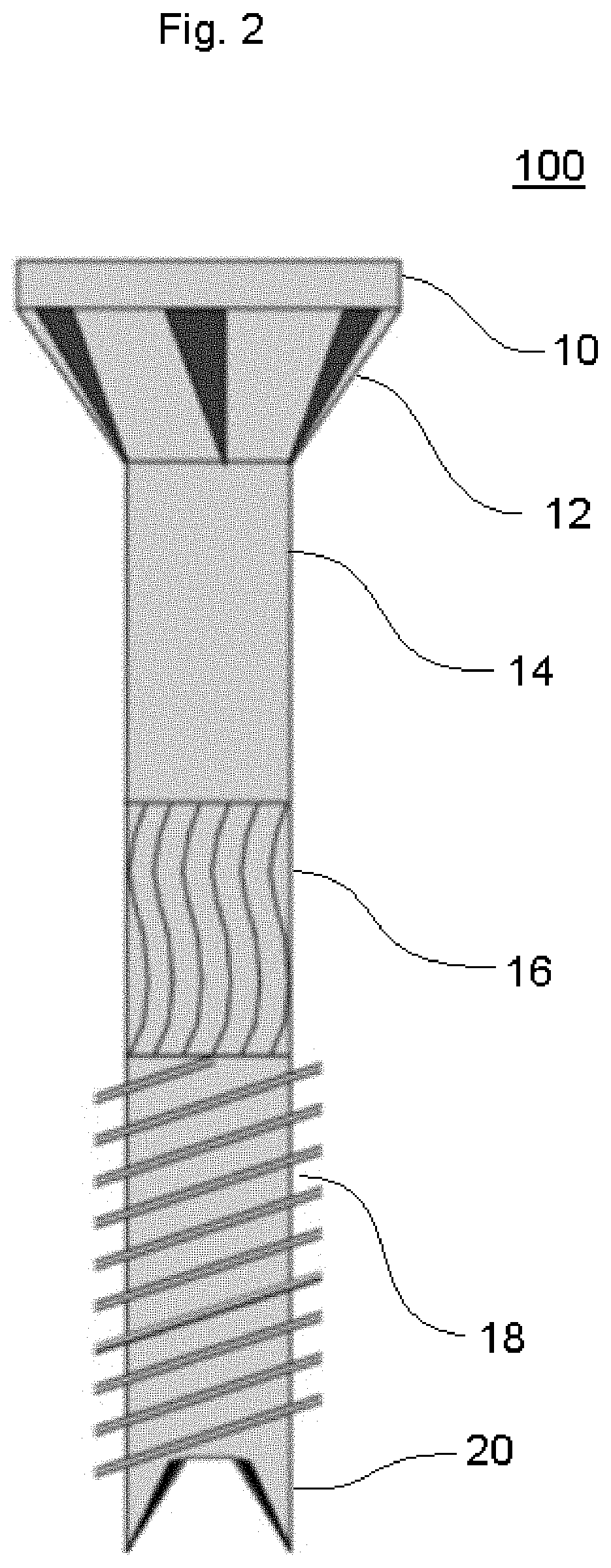
[0028]FIG. 2 is a side view of a screw 100. The screw 100 has a head 10. The head 10 is a self countersinking. The head 10 includes countersinking nibs 12. The self-countersinking head reduces risks of stress risers and over aggressive countersinking of cortical bone while limiting cortical stress. The shank 14 of the screw 100 includes a knurled portion 16. The knurled portion 16 allows for reduced friction and drag upon insertion of the screw 100.

[0029]Like all surgical screws, the screw 100 has a threaded portion 18. The threaded portion 18 is preferably a self tapping thread. The end of the screw 100 has sharp cutting flutes 20. The cutting flutes 20 allow for the self drilling and self tapping of the screw 100. Because the screw 100 is self drilling and self tapping, it has increased pull out strength so that it can provide greater overall compression than a screw that is inserted in a predrilled hole.

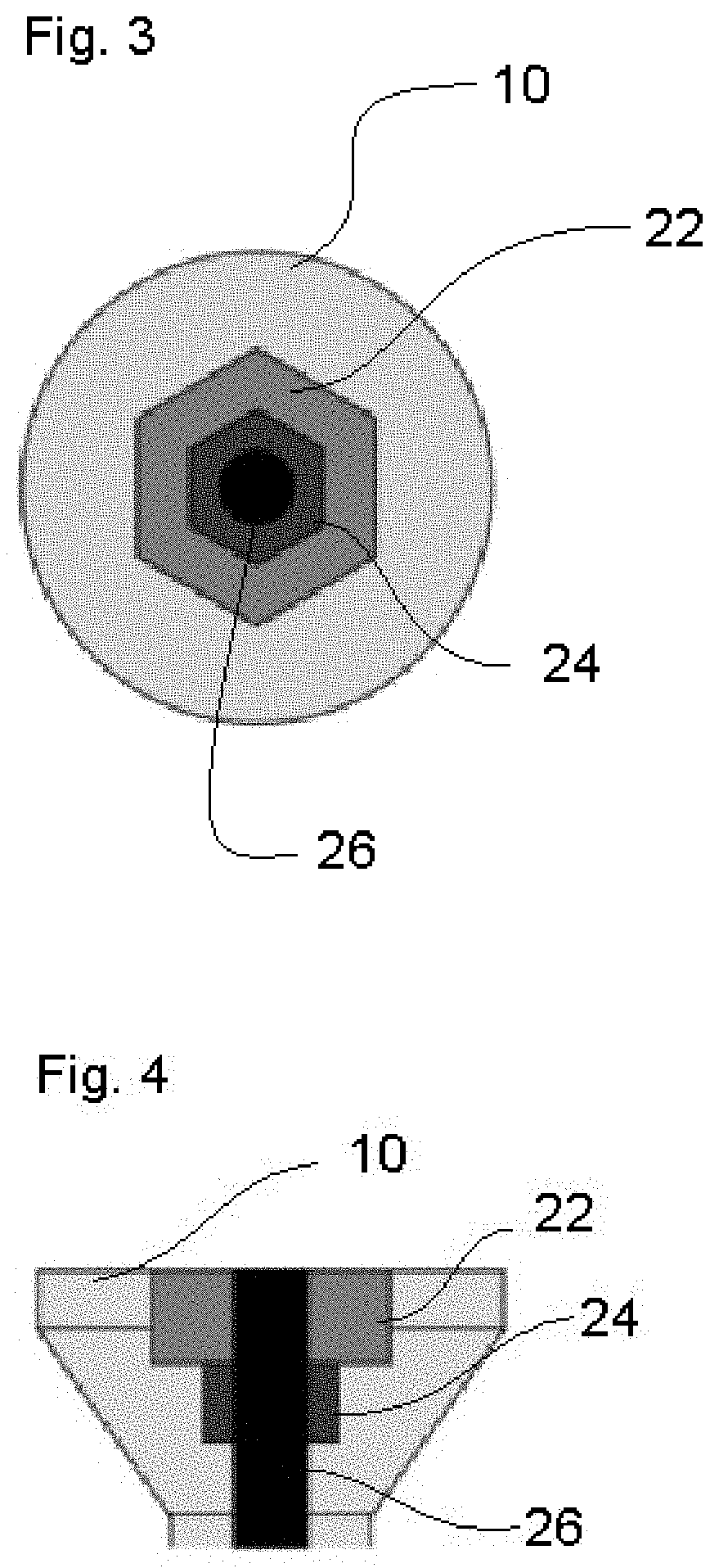
[0030]FIG. 3 is a top view the head 10 of the screw 100. As shown, the head 1...


PUM


Abstract

A surgical screw that is self-countersinking, self-tapping/fluted, self-drilling, and having a knurled shank designed for one step insertion. The screw has a stepped driving portion.

Description

CROSS REFERENCE TO RELATED APPLICATIONS[0001]This application claims the benefit of U.S. Provisional Application No. 62 / 958,581, filed Jan. 8, 2020.FIELD OF THE INVENTION[0002]The present Invention relates to surgical screws and more specifically to a self tapping surgical screw and a method of installing the same.BACKGROUND OF THE INVENTION[0003]Many fracture and reconstruction surgeries involves open reduction and internal fixation (ORIF). An incision is made over the area to see the fractured bones. Like a jigsaw puzzle, the pieces of the broken bones are placed back together (open reduction). The broken bones are then held together (internal fixation) in this correct position with metal plates and / or screws. This internal fixation provides stability so movement can begin shortly after surgery as the fracture heals.[0004]Plates and screws used to fix a fracture are not removed as long as they are not causing problems. Most people do not have problems with the plate and screws. In...

Claims


Application Information

Patent Timeline
Patent Type & Authority Applications(United States)
IPC IPC(8): A61B17/86A61B17/88
CPCA61B17/863A61B17/8615A61B2017/681A61B17/8888A61B17/8897A61B17/864A61B17/8605A61B17/8625A61B17/8635A61B17/865
Inventor EPSTEIN, JOSHUAROLAND, DERRICK
Owner EPSTEIN JOSHUA
Why Eureka
Try Eureka