Fluid composition sensor device and method of using the same

a technology of composition sensor and fluid composition, which is applied in the direction of suspension and porous material analysis, instruments, material analysis, etc., can solve the problem that existing fluid sensor devices provide limited functionality in generating data indicativ

Active Publication Date: 2021-07-22
HONEYWELL INT INC
View PDF11 Cites 6 Cited by
  • Summary
  • Abstract
  • Description
  • Claims
  • Application Information

AI Technical Summary

Benefits of technology

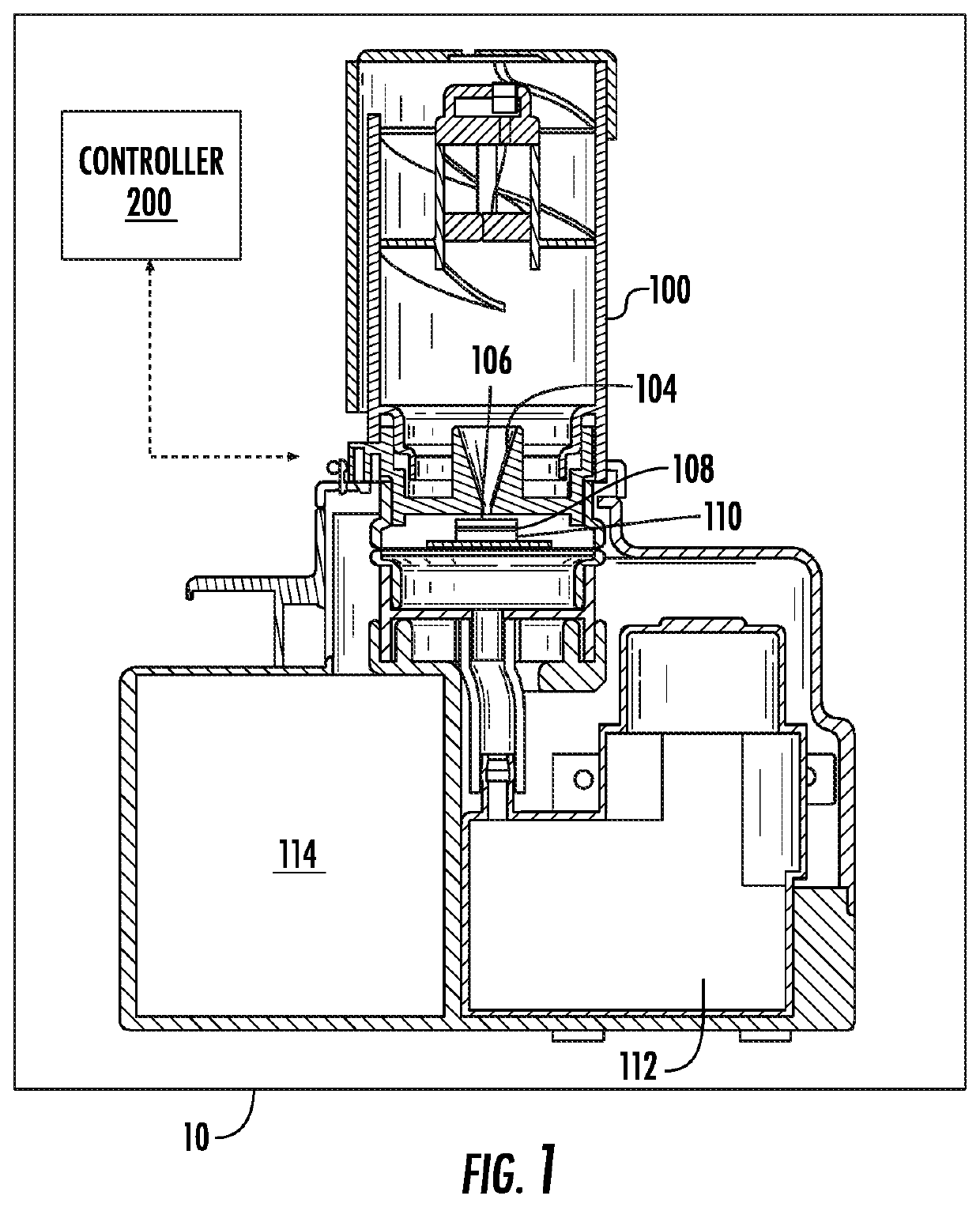
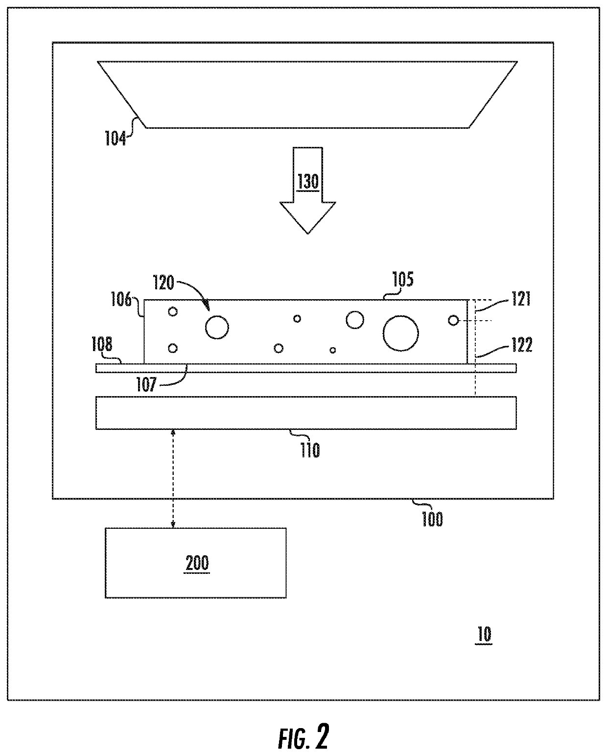
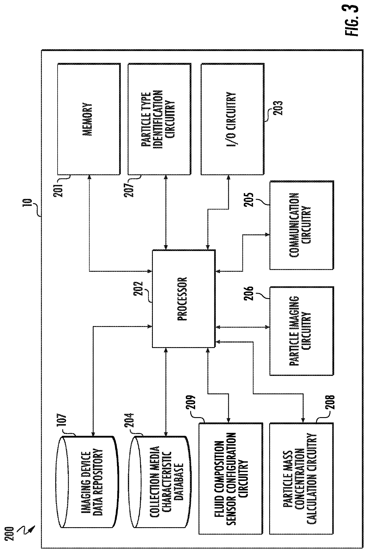
[0006]Various embodiments are directed to a device for detecting fluid particle characteristics comprising: a fluid composition sensor configured to receive a volume of fluid, the fluid composition sensor comprising: a housing defining an internal sensor portion and comprising a fluid inlet configured to receive the volume of fluid; at least one collection media configured to receive one or more particles of a plurality of particles within the volume of fluid, at least a portion of the at least one collection media being disposed within the internal sensor portion; an impactor nozzle disposed within the internal sensor portion, the impactor nozzle comprising: a nozzle inlet comprising a nozzle inlet cross-sectional area, the nozzle inlet being configured to receive at least a portion of the volume of fluid; a nozzle outlet comprising a nozzle outlet cross-sectional area; and a plurality of sidewalls extending between the nozzle inlet and the nozzle outlet, each of the plurality of sidewalls comprising an inner sidewall and an outer sidewall; wherein the impactor nozzle is configured such that the at least a portion of the volume of fluid received by the nozzle inlet flows from the nozzle outlet in fluid flow direction at least substantially toward the at least a portion of the at least one collection media disposed within the internal sensor portion; at least one illumination source configured to emit one or more light beams so as to engage the at least one collection media and illuminate the one or more particles received by the at least one collection media, each of the one or more light beams being emitted from the illumination source at a corresponding light beam emission angle; and an imaging device configured to capture an image of at least a portion of the one or more particles received by the at least one collection media; and a controller configured to determine at least one particle characteristic of the volume of fluid received by the fluid composition sensor based at least in part on the image captured by the imaging device; wherein the fluid composition sensor is configured such that at least a portion of the one or more light beams emitted from the illumination source extend through both the nozzle inlet and the nozzle outlet; wherein the impactor nozzle comprises a particle imaging configuration wherein at least one of the plurality of sidewalls is defined at least in part by a taper angle corresponding with the light beam emission angle of one of the one or more light beams, wherein the taper angle is at least as large as each light beam emission angle.
[0007]In various embodiments, the plurality of sidewalls may define a first nozzle portion and a second nozzle portion, wherein the first nozzle portion comprises a first tapered portion extending between the nozzle inlet and an intermediate nozzle location, and wherein the second nozzle portion extends between the intermediate nozzle location and the nozzle outlet, the intermediate nozzle location comprising an intermediate nozzle cross-sectional width, wherein the first nozzle portion is configured such that the intermediate nozzle cross-sectional width is smaller than the nozzle inlet cross-sectional area. In various embodiments, the second nozzle portion may comprise a second tapered portion configured such that the intermediate nozzle cross-sectional width is smaller than the nozzle outlet cross-sectional area. Further, in various embodiments, the impactor nozzle may further comprise a central nozzle axis extending perpendicularly between the nozzle inlet and the nozzle outlet, wherein the illumination source is aligned with the central nozzle axis.
[0008]In various embodiments, the impactor nozzle may be configurable between a first nozzle configuration and a second nozzle configuration, wherein the first nozzle configuration corresponds to a particle collection functionality of the fluid composition sensor, and wherein the second nozzle configuration corresponds to a particle analysis functionality of the fluid composition sensor, wherein the fluid composition sensor is configured so as to selectively configure the nozzle between the first nozzle configuration and the second nozzle configuration. In various embodiments, the nozzle outlet cross-sectional area of the nozzle outlet in the first nozzle configuration is smaller than the nozzle outlet cross-sectional area of the nozzle outlet in the second nozzle configuration. Further, In various embodiments, each of the plurality of sidewalls may be configured to independently move relative to an adjacent sidewall of the plurality of sidewalls. In various embodiments, the fluid composition sensor may be configured to selectively apply a pushing force to each of the outer sidewalls of the plurality of sidewalls.
[0009]Various embodiments are directed to a collection media assembly for receiving one or more particles from a volume of fluid within a fluid composition sensor, the collection media assembly comprising: a transparent substrate; at least one collection media disposed upon the transparent substrate and configured to receive one or more particles from a volume of fluid; at least one orifice extending through the transparent substrate, the at least one orifice being arranged at least approximately adjacent a corresponding collection media of the at least one collection media; and at least one air seal engagement portion, each air seal engagement portion being configured to surround one of the at least one collection media and the at least one orifice corresponding thereto; wherein the at least one orifice is configured to enable the volume of fluid to flow through the transparent substrate; and wherein each of the at least one seal engagement portions is configured to engage one or more air seal components of a fluid composition sensor such that substantially all of the volume of fluid flows through the at least one orifice surrounded by the at least one air seal engagement portion.
[0010]Various embodiments are directed to a method for detecting fluid particle characteristics comprising: receiving, via a sensor, a volume of fluid; directing the volume of fluid, via an impactor nozzle in a first nozzle configuration, toward a collection media, receiving, via the collection media, one or more particles of a plurality of particles within the volume of fluid; reconfiguring the impactor nozzle to a second nozzle configuration; illuminating, via one or more light beams emitted from an illumination source, the one or more particles received by the collection media, wherein each of the one or more light beams are emitted from an illumination source at a corresponding light beam emission angle; capturing an image of the one or more particles of the plurality of particles received by the collection media; and determining, based at least in part on the image, at least one particle characteristic of the plurality of particles of volume of fluid.
[0011]In various embodiments, reconfiguring the impactor nozzle to the second nozzle configuration may comprise repositioning at least a portion of the impactor nozzle such that at least a portion of one or more of a plurality of sidewalls of the impactor nozzle is defined at least in part by a taper angle corresponding with the light beam emission angle of one of the one or more light beams, wherein the taper angle is at least as large as each of the light beam emission angles. In various embodiments, the method may further comprise, upon capturing the image of the one or more particles of the plurality of particles received by the collection media, repositioning a second collection media so as to replace the collection media.

Problems solved by technology

However, existing fluid sensor devices provide limited functionality in generating data indicative of certain characteristics of fluids, such as the unique identity and concentration of individual particles contained within a fluid flow.

Method used


Image

  • Fluid composition sensor device and method of using the same
  • Fluid composition sensor device and method of using the same
  • Fluid composition sensor device and method of using the same

Examples


Embodiment Construction

[0033]The present disclosure more fully describes various embodiments with reference to the accompanying drawings. It should be understood that some, but not all embodiments are shown and described herein. Indeed, the embodiments may take many different forms, and accordingly this disclosure should not be construed as limited to the embodiments set forth herein. Rather, these embodiments are provided so that this disclosure will satisfy applicable legal requirements. Like numbers refer to like elements throughout.

[0034]It should be understood at the outset that although illustrative implementations of one or more aspects are illustrated below, the disclosed assemblies, systems, and methods may be implemented using any number of techniques, whether currently known or not yet in existence. The disclosure should in no way be limited to the illustrative implementations, drawings, and techniques illustrated below, but may be modified within the scope of the appended claims along with the...


PUM

PropertyMeasurementUnit
thicknessaaaaaaaaaa
thicknessaaaaaaaaaa
taper angleaaaaaaaaaa

Abstract

Various embodiments described herein relate to apparatuses and methods for detecting fluid particles and their characteristics. In various embodiments, a device for detecting fluid particles and their characteristics may comprise a lens free holographic microscope configured to collect fluid particles via inertial impaction. In various embodiments, the collection media may be replaceable within the apparatus. In various embodiments, the impactor nozzle may be selectively configured to avoid optical reflections and scattering from illumination light passing through the nozzle. Various embodiments are directed to a collection media assembly for receiving particles from a volume of fluid within a fluid composition sensor. A collection media assembly may comprise a collection media, an orifice, a seal engagement portion and a frame element configured to facilitate the serial use of a plurality of collection media assemblies within a fluid composition sensor.

Description

BACKGROUND[0001]Sensors and devices may be utilized to characterize various aspects of fluids in a wide variety of applications. As just one example, sensor devices may be utilized for monitoring air conditions, such as monitoring and characterizing the particulate content of a flow of air. However, existing fluid sensor devices provide limited functionality in generating data indicative of certain characteristics of fluids, such as the unique identity and concentration of individual particles contained within a fluid flow. Fluid sensor devices can use holographic imaging methods to characterize particle identity and concentration of particulate matter that has been collected via inertial impaction. It is desirable to improve various aspects of particle sampling and analysis. In general, it can be advantageous for a fluid sampling device to utilize a sampling media that enables rapid and / or simplified sequential sampling of particles. For devices utilizing holographic imaging (such ...

Claims


Application Information

Patent Timeline
Patent Type & Authority Applications(United States)
IPC IPC(8): G01N15/02
CPCG01N15/0227G01N2015/0233G01N15/06G01N2015/0693G01N1/2208G01N1/2273G01N1/2247G01N2001/2223G01N2015/0046G01N15/1434G01N2015/1454G01N15/1463G01N2015/1493G01N2015/1497G01N15/0612G01N15/1429
Inventor BROWN, ANDY WALKERSPELDRICH, JAMIE W.MYERS, RONALD W.SORENSON, RICHARD CHARLES
Owner HONEYWELL INT INC
Why Eureka
Try Eureka