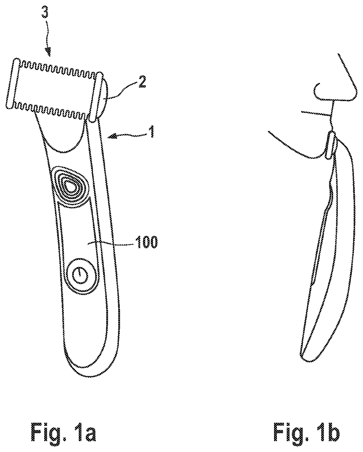
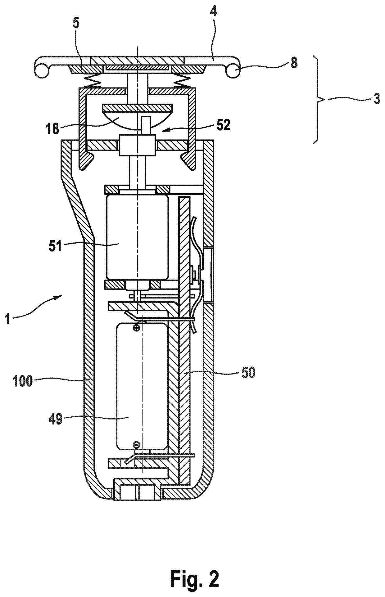
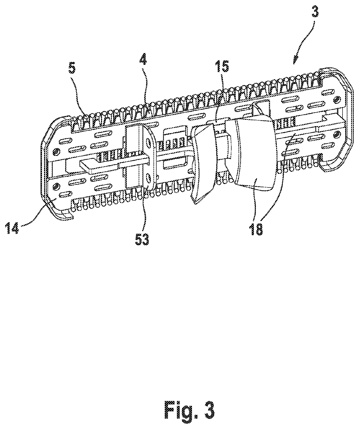
Electric beard trimmer

a technology of electric shaver and electric trimmer, which is applied in the direction of metal working devices, etc., can solve the problems of bulky protection elements, lateral edges may irritate the skin, and skin irritation, and achieve good control of edging contours, avoid skin irritation, and glide comfortably along the skin

Pending Publication Date: 2021-07-29
BRAUN GMBH
View PDF27 Cites 2 Cited by
  • Summary
  • Abstract
  • Description
  • Claims
  • Application Information

AI Technical Summary

Benefits of technology

[0011]It is an objective underlying the present invention to provide for an improved cutter system avoiding at least one of the disadvantages of the prior art and / or further developing the existing solutions. A more particular objective underlying the invention is to provide for a close and thorough cutting of longer stubbles and hair including a good control of edging contours and, at the same time, avoiding skin irritations and achieving comfortable gliding along the skin. Another objective underlying the present invention is an efficient manufacturing of the lateral protection elements. Still further objective is a support structure for supporting the cooperating cutting elements with low friction between the cutting elements, low temperatures of the cutting teeth and low energy consumption and thus long energy storage life, and at the same time allowing for easy assembling of the cutter elements with the lateral protection elements.

Problems solved by technology

Due to the often exposed arrangement of the blades, not only the tips of the teeth, but also the lateral edges of the cutting elements may cause skin irritations.
When the cutter system glides along the skin surface, said lateral edges may irritate the skin even when the corners or transition portions from the lateral edges to the toothed edges are rounded.
Such lateral protection elements, on the one hand, should reliably protect the skin against irritations and therefore, the lateral end protection elements usually include rather large roundings and chamfered contours which, however, often make the protection elements bulky and increasing the size of the end portions.
Fulfilling such various performance issues at the same time is quite difficult.

Method used


Image

  • Electric beard trimmer
  • Electric beard trimmer
  • Electric beard trimmer

Examples


Embodiment Construction

[0036]So as to avoid steps and / or protrusions at the skin contact surface detrimental to close and thorough cutting, at least one of said lateral protection elements may be integrally formed in one part with the cutting element by an end portion of said cutting element bent or curved away from the skin contact surface and enveloping a gap receiving the other cutting element and / or enveloping the support element supporting the cutting elements. So as to avoid the protrusion of a plastic end cap slipped onto the cutting element and protruding towards the skin to be contacted, the lateral end portions of the cutting element may be bent or curved away from the skin contact surface to form the rounded and / or chamfered lateral protection element themselves. More particularly, the lateral protection elements may be formed homogeneously with and / or from the same material as the cutting element including the toothed cutting edges, wherein forming the lateral protection elements by means of b...


PUM


Abstract

The present invention relates to a cutter system for an electric shaver and/or trimmer, comprising a pair of comb-like cutting elements with cooperating toothed cutting edges and movably supported relative to each other by a support element, wherein lateral ends of at least one of said cutting elements are provided with lateral protection elements having rounded and/or chamfered edge contours for soft skin engagement, wherein said lateral protection element is integrally formed in one part with the cutting element by an end portion of the cutting element bent away from a skin contact surface thereof and enveloping a gap movably receiving the other cutting element and/or enveloping the support element.

Description

FIELD OF THE INVENTION[0001]The present invention relates to cutting body hair such as beard stubbles of multidays' beard. More particularly, the present invention relates to a cutter system for an electric shaver and / or trimmer, comprising a pair of comb-like cutting elements with cooperating toothed cutting edges and movably supported relative to each other by a support element, wherein lateral ends of at least one of said cutting elements are provided with lateral protection elements having rounded and / or chamfered edge contours for soft skin engagement. The present invention also relates to a method of manufacturing such cutter system and to an electric shaver and / or trimmer provided with such a cutter system.BACKGROUND OF THE INVENTION[0002]Electric shavers and trimmers utilize various mechanisms to provide hair cutting functionality. Some electric shavers include a perforated shear foil cooperating with an undercutter movable relative thereto so as to cut hairs entering the pe...

Claims


Application Information

Patent Timeline
Patent Type & Authority Applications(United States)
IPC IPC(8): B26B19/38B26B19/20
CPCB26B19/3846B26B19/06B26B19/3893B26B19/205B26B19/042B26B19/046B26B19/10
Inventor KOEPPL, ALOISEICHHORN, REINHOLDSCHMITT, JANAFUELLGRABE, MARTIN
Owner BRAUN GMBH
Why Eureka
Try Eureka