Biostimulator having low-polarization electrode(s)

a biostimulator and electrode technology, applied in the field of leadless biostimulators, can solve the problems of complicated lead connectors, mechanical failure risks, and conventional pacemakers, and achieve the effects of minimizing power consumption, effective pacing, and maximizing pacer longevity

Active Publication Date: 2021-10-07
PACESETTER INC
View PDF10 Cites 1 Cited by
  • Summary
  • Abstract
  • Description
  • Claims
  • Application Information

AI Technical Summary

Benefits of technology

The technical effect of this patent is to improve the lifespan of leadless cardiac pacemakers by reducing their power consumption through the use of autocapture technology. This requires accurate detection of the chambers' evoked responses to ensure successful implantation.

Problems solved by technology

The technical problem addressed in this patent text relates to improving cardiac pacing therapy through the development of leadless cardiac pacemakers. These devices offer several advantages over traditional pace makers including reduced complexity and risk of mechanical failures but also face limitations related to battery life and their ability to be easily delivered into the heart.

Method used


Image

  • Biostimulator having low-polarization electrode(s)
  • Biostimulator having low-polarization electrode(s)
  • Biostimulator having low-polarization electrode(s)

Examples


Embodiment Construction

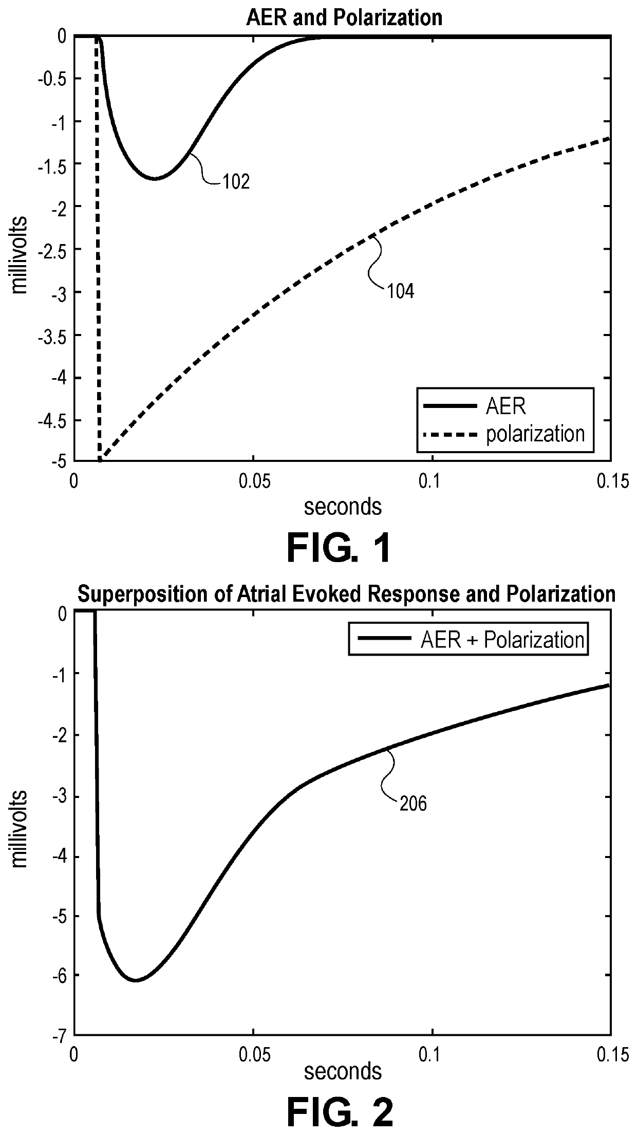
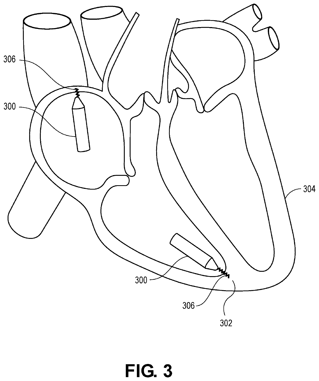
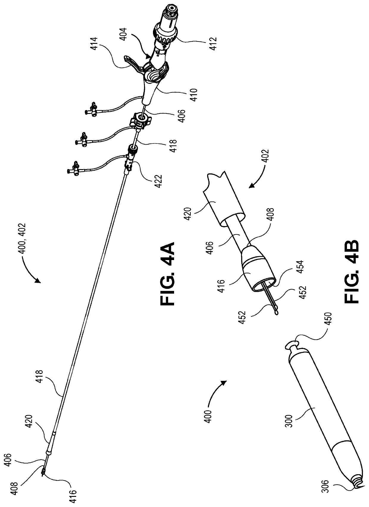
[0029]Embodiments describe a biostimulator having electrode(s) coated with low-polarization coating(s). The biostimulator may be a leadless biostimulator, such as a leadless cardiac pacemaker used to pace cardiac tissue. The biostimulator may, however, be used in other applications, such as deep brain stimulation. Thus, reference to the biostimulator as being a cardiac pacemaker is not limiting. Furthermore, reference to the biostimulator as being used to detect an atrial evoked response is not to be limiting of the applications of the biostimulator because the biostimulator may be used to detect other tissue or chamber evoked responses, such as a ventricular evoked response. More particularly, the biostimulator may be implanted in an atrium, a ventricle, or another body tissue of a heart.

[0030]In various embodiments, description is made with reference to the figures. However, certain embodiments may be practiced without one or more of these specific details, or in combination with ...


PUM


Abstract

A biostimulator, such as a leadless pacemaker, having electrode(s) coated with low-polarization coating(s), is described. A low-polarization coating including titanium nitride can be disposed on an anode, and a low-polarization coating including a first layer of titanium nitride and a second layer of platinum black can be disposed on a cathode. The anode can be an attachment feature used to transmit torque to the biostimulator. The cathode can be a fixation element used to affix the biostimulator to a target tissue. The low-polarization coating(s) impart low-polarization to the electrode(s) to enable an atrial evoked response to be detected and used to effect automatic output regulation of the biostimulator. Other embodiments are also described and claimed.

Description


Claims


Application Information

Patent Timeline
Owner PACESETTER INC
Why Eureka
Try Eureka