Refrigerator and control method therefor

a technology of refrigerators and controls, which is applied in the field of refrigerators, can solve the problems of increasing the heating amount of the heater, and difficulty in making ice with uniform transparency according to the shape of ice, and achieves the effects of uniform transparency, delayed ice making rate, and uniform transparency

Pending Publication Date: 2021-11-11
LG ELECTRONICS INC
View PDF1 Cites 2 Cited by
  • Summary
  • Abstract
  • Description
  • Claims
  • Application Information

AI Technical Summary

Benefits of technology

[0043]According to the embodiments, since the heater is turned on in at least a portion of the sections while the cold air supply part supplies cold air, the ice making rate may be delayed by the heat of the heater so that the bubbles dissolved in the water inside the ice making cell move toward the liquid water from the portion at which the ice is made, thereby making the transparent ice.
[0044]Particularly, according to the embodiments, one or more of the cooling power of the cold air supply part and the heating amount of heater may be controlled to vary according to the mass per unit height of water in the ice making cell to make the ice having the uniform transparency as a whole regardless of the shape of the ice making cell.
[0045]Also, the heating amount of transparent ice heater and / or the cooling power of the cold air supply part may vary in response to the change in the heat transfer amount between the water in the ice making cell and the cold air in the storage chamber, thereby making the ice having the uniform transparency as a whole.

Problems solved by technology

When growth of the transparent ice proceeds to reduce a volume of the water within the ice making block, the solidification rate is gradually increased, and thus, sufficient convection suitable for the solidification rate may not occur.
However, according to the prior art document 2, when only the volume of water is reduced, the heating amount of heater may increase, and thus, it may be difficult to make ice having uniform transparency according to shapes of ice.

Method used


Image

  • Refrigerator and control method therefor
  • Refrigerator and control method therefor
  • Refrigerator and control method therefor

Examples


Embodiment Construction

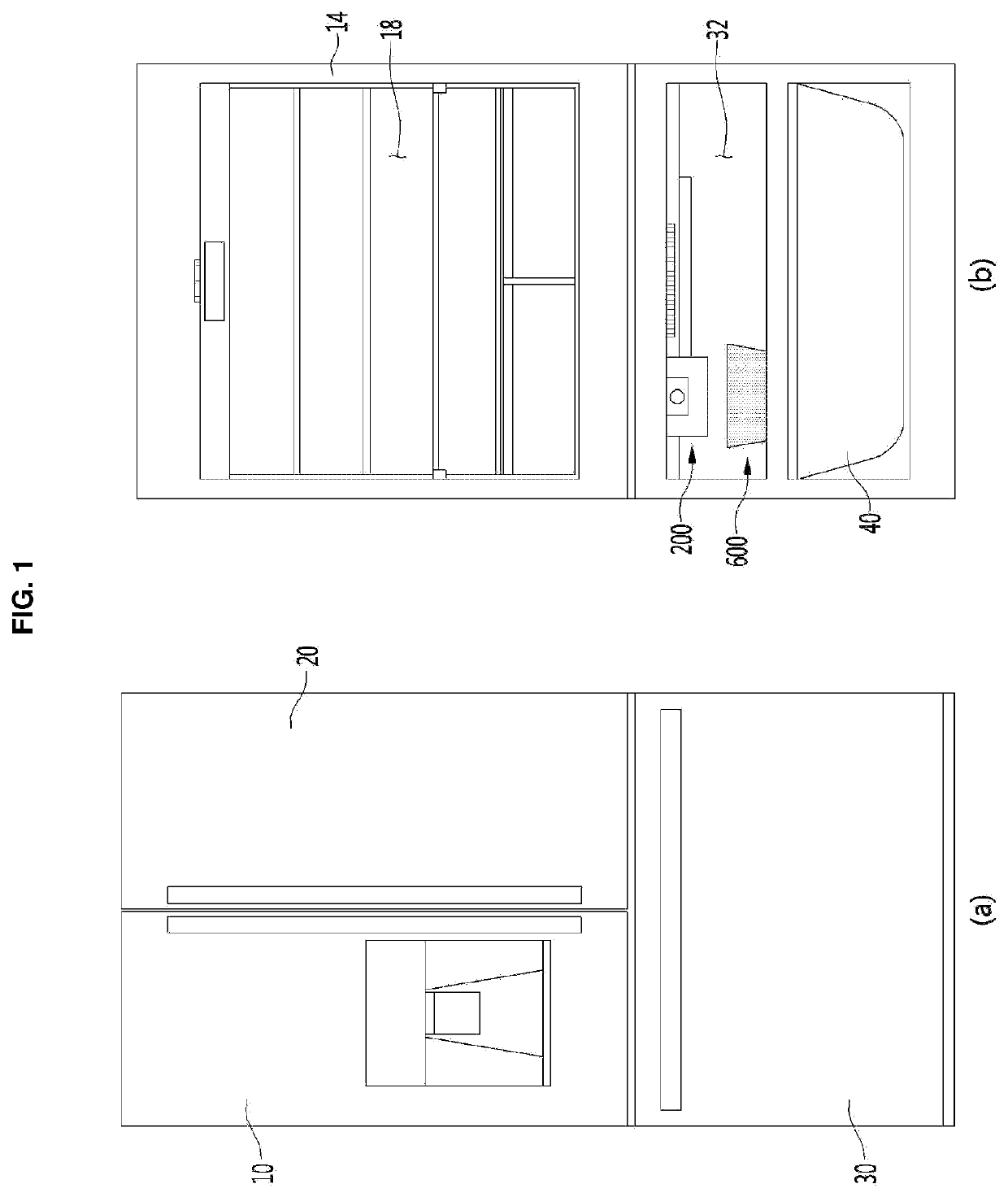
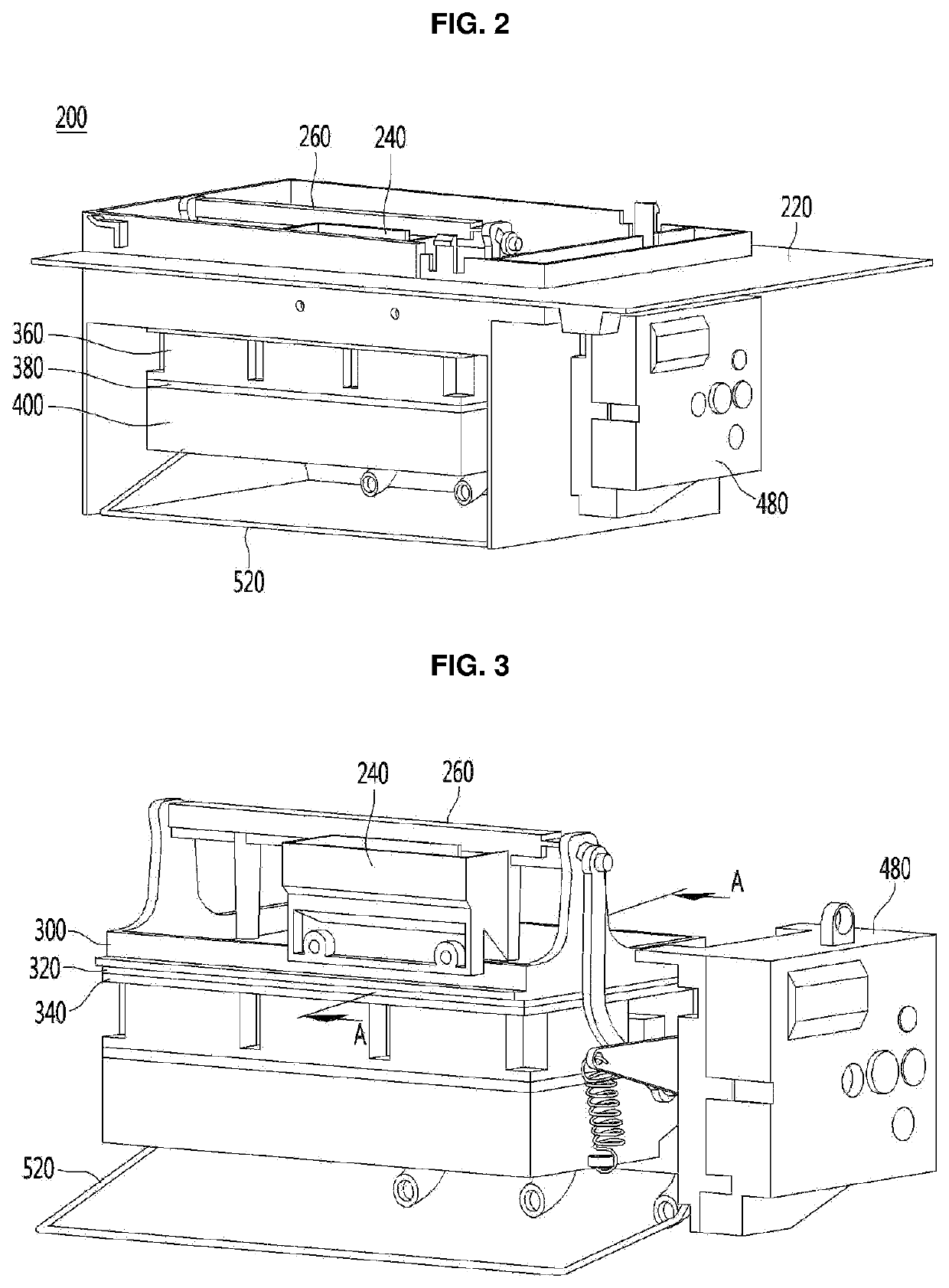
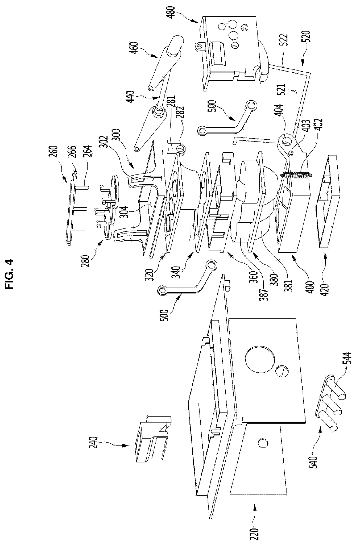
[0063]Hereinafter, some embodiments of the present invention will be described in detail with reference to the accompanying drawings. Exemplary embodiments of the present invention will be described below in more detail with reference to the accompanying drawings. It is noted that the same or similar components in the drawings are designated by the same reference numerals as far as possible even if they are shown in different drawings. Further, in description of embodiments of the present disclosure, when it is determined that detailed descriptions of well-known configurations or functions disturb understanding of the embodiments of the present disclosure, the detailed descriptions will be omitted.

[0064]Also, in the description of the embodiments of the present disclosure, the terms such as first, second, A, B, (a) and (b) may be used. Each of the terms is merely used to distinguish the corresponding component from other components, and does not delimit an essence, an order or a seq...


PUM


Abstract

The refrigerator of the present invention comprises: a storage compartment where food is stored; a cold air supply means for supplying cold air to the storage compartment; a first tray forming a part of an ice making cell which is a space where water phase-changes into ice by the cold air; a second tray which forms another part of the ice making cell and which can be brought into contact with the first tray during an ice making process, and which is connected to a driving unit so as to be spaced apart from the first tray during an ice separating process; a heater positioned adjacent to at least one of the first tray and the second tray; an ice bin for storing ice dropped from the ice making cell; a full ice level sensing means for sensing a full ice level of the ice bin; and a control unit for controlling the heater and the driving unit.When the full ice level of the ice bin is sensed by the full ice level sensing means, the control unit controls the driving unit such that the second tray moves to the ice separating position after the ice making is completed.

Description

TECHNICAL FIELD[0001]The present disclosure relates to a refrigerator and a control method therefor.BACKGROUND ART[0002]In general, refrigerators are home appliances for storing food at a low temperature in a storage space that is covered by a door. The refrigerator may cool the inside of the storage space by using cold air to store the stored food in a refrigerated or frozen state. Generally, an ice maker for making ice is provided in the refrigerator. The ice maker makes ice by cooling water after accommodating the water supplied from a water supply source or a water tank into a tray. The ice maker separates the made ice from the ice tray in a heating manner or twisting manner.[0003]The ice maker through which water is automatically supplied, and the ice automatically separated may be, for example, opened upward so that the mode ice is pumped up.[0004]As described above, the ice made in the ice maker may have at least one flat surface such as crescent or cubic shape.[0005]When the...

Claims


Application Information

Patent Timeline
Patent Type & Authority Applications(United States)
IPC IPC(8): F25C1/18F25C1/24F25C5/08
CPCF25C1/18F25C1/24F25C5/08F25C2700/14F25C2400/14F25C2600/04F25C2400/10F25C5/187F25C2305/022F25D2400/02
Inventor LEE, DONGHOONLEE, WOOKYONGYEOM, SEUNGSEOBBAE, YONGJUNSON, SUNGGYUNPARK, CHONGYOUNG
Owner LG ELECTRONICS INC
Why Eureka
Try Eureka