Motorized rotating transducer mount

a transducer and motor technology, applied in the field of transducers, can solve problems such as the transducer being turned towards an undesirable location

Active Publication Date: 2021-11-25
RIDL MARK ALAN
View PDF0 Cites 2 Cited by
  • Summary
  • Abstract
  • Description
  • Claims
  • Application Information

AI Technical Summary

Problems solved by technology

However, the direction of the transducer is directly affected by the direction of the motor, and when the motor turns the transducer may be turned towards an undesirable location.

Method used


Image

  • Motorized rotating transducer mount
  • Motorized rotating transducer mount
  • Motorized rotating transducer mount

Examples


Embodiment Construction

[0014]The following detailed description is of the best currently contemplated modes of carrying out exemplary embodiments of the invention. The description is not to be taken in a limiting sense, but is made merely for the purpose of illustrating the general principles of the invention, since the scope of the invention is best defined by the appended claims.

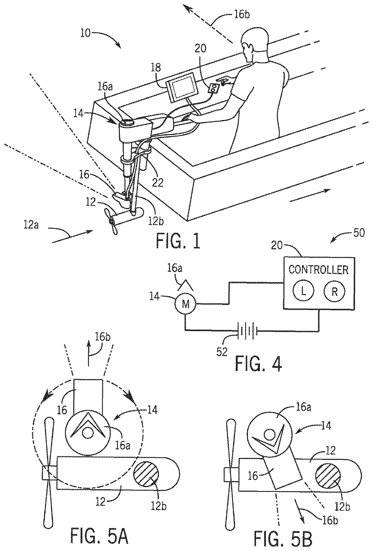
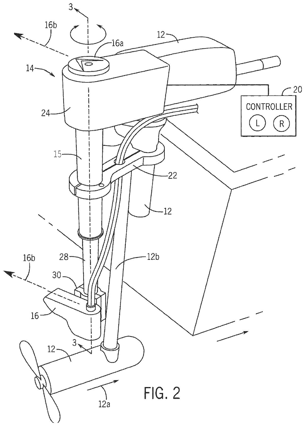
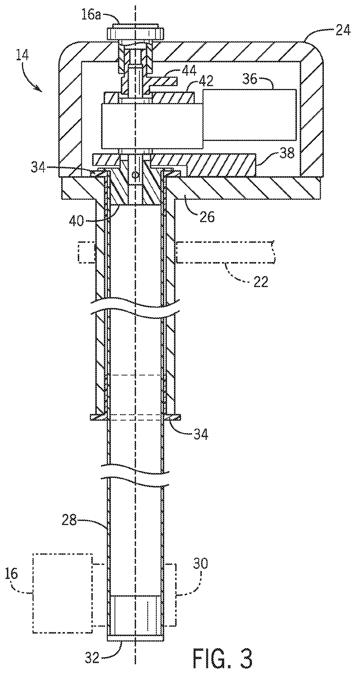
[0015]Referring to FIGS. 1 through 5B, the present invention includes a transducer mount assembly 10. The transducer mount assembly 10 includes a housing 14 and a motor 36 coupled to and disposed within the housing 14. An elongated rod 28 extends from the housing 14 and is operably coupled to the motor 36. The motor 36 is configured to rotate the elongated rod 28 about a longitudinal axis of the elongated rod 28 in a first direction and a second direction opposite the first direction. A controller 20 is in communication with the motor 36 and is configured to selectively direct the motor to rotate the elongated rod 28 in the firs...


PUM


Abstract

A transducer mount assembly includes a housing and a motor coupled to and disposed within the housing. An elongated rod extends from the housing and is operably coupled to the motor. The motor is configured to rotate the elongated rod about a longitudinal axis of the elongated rod in a first direction and a second direction opposite the first direction. A controller is in communication with the motor and is configured to selectively direct the motor to rotate the elongated rod in the first direction and the second direction. A boat mount bracket is configured to couple the transducer mount assembly to portion of a boat. A transducer mount bracket is configured to couple a transducer to the elongated rod.

Description

BACKGROUND OF THE INVENTION[0001]The present invention relates to transducers and, more particularly, to a motorized rotating transducer mount.[0002]Sonar (SOund Navigation And Ranging) has long been used to detect waterborne or underwater objects. For example, sonar devices may be used to determine depth and bottom topography, detect fish, locate wreckage, etc. In this regard, due to the extreme limits to visibility underwater, sonar is typically the most accurate way to locate objects underwater. Sonar transducer elements, or simply transducers, convert electrical energy into sound or vibrations at a particular frequency. A sonar sound beam is transmitted into and through the water and is reflected from objects it encounters. The transducer receives the reflected sound (the “sonar returns”) and converts the sound energy into electrical energy. Based on the known speed of sound, it is possible to determine the distance to and / or location of the waterborne or underwater objects. The...

Claims


Application Information

Patent Timeline
Patent Type & Authority Applications(United States)
IPC IPC(8): B63H20/00
CPCB63H20/007B63B2201/18B63H20/12
Inventor RIDL, MARK ALAN
Owner RIDL MARK ALAN
Why Eureka
Try Eureka