Shoulder prosthesis components and assemblies

a technology for shoulder prostheses and components, applied in the field of shoulder prostheses, can solve the problems of excessive patient bone loss, disassembly or breakage of the construction, etc., and achieve the effect of flexible working

Pending Publication Date: 2021-12-30
HOWMEDICA OSTEONICS CORP
View PDF7 Cites 3 Cited by
  • Summary
  • Abstract
  • Description
  • Claims
  • Application Information

AI Technical Summary

Benefits of technology

[0007]In one embodiment, a humeral anchor is disclosed. The humeral anchor can include a first end and a second end opposite the first end, the second end disposed farthest into the humerus when the humeral anchor is implanted. The humeral anchor can include an interior surface open at the first end and extending between the first end and the second end, the interior surface disposed about a recess disposed between the first end and the second end. The humeral anchor can include at least one fin disposed at the second end and configured to reduce, minimize or eliminate rotation of the humeral anchor when the humeral anchor is implanted in bone of a humerus. The recess can be configured to secure a coupling of a shoulder articular body directly to the interior surface.
[0018]In some embodiments, a transverse surface can be configured to engage a humeral bone layer exposed by resection or other preparation when the humeral anchor is implanted to resist subsidence. The transverse surface can comprise a portion of a collar disposed at the first end of the humeral anchor. The transverse surface can comprise an anti-rotation feature disposed between the first end and the second end of the humeral anchor. The interior surface can comprise a tapered surface for engaging an articular assembly. The interior surface can be disposed about the interior surface comprises a slot for engaging an articular assembly. An exterior surface having a porous surface can be at least partially bounded by a non-porous edge, the non-porous edge being disposed between the porous surface and the second end. The interior surface can comprise a first taper disposed towards the first end and a second taper disposed towards the second end. An exterior surface having a first tapered portion can be disposed about the first end and a second tapered portion can be disposed about a portion of the humeral anchor between the first tapered portion and the second end of the humeral anchor, the second tapered portion being discontinuous from the first tapered portion. The first tapered portion can have a first angle away from an axis disposed from the first end to the second end and the second tapered portion can have a second angle away from the axis disposed from the first end to the second end, the second angle being greater than the first angle. The interior surface can comprise a groove configured to receive a locking ring of an articular body assembly. In some embodiments, the humeral anchor can include a plurality of struts disposed about an exterior surface of the humeral anchor between the first end and the second end. A porous surface can be disposed between at least two struts of the plurality of struts. A plurality of struts can be disposed about an exterior surface of the humeral anchor. The exterior surface can have a first portion disposed about the first end and a second portion between the first portion and the second end of the humeral anchor, the struts being disposed about the first portion. A first plurality of struts can be disposed about the first portion and at least one strut is disposed about the second portion. The first plurality of struts can have twice as many struts as the second plurality of struts. The struts can be disposed about the second portion. The struts can be configured to reduce, minimize or eliminate rotation of the humeral anchor.
[0020]In some embodiments, the humeral anchor can have at least one fin configured to reduce, minimize or eliminate rotation of the humeral anchor when the humeral anchor is implanted in bone of a humerus. The fin can be disposed at the second end of the humeral anchor. In some embodiments, an array of fins can be disposed radially at the second end of the humeral anchor.

Problems solved by technology

In prosthesis that are converted from anatomic to reverse by a modularity below the plane of resection, removal of anatomic devices that have integrated into the patient's bony anatomy proves to be difficult for the surgeon, and could potentially cause excessive patient bone loss.
Such construct are typically made of three (3) components that present an extra modularity in comparison to a two (2) component construct and could potentially cause disassembly or breakage of the construct.

Method used


Image

  • Shoulder prosthesis components and assemblies
  • Shoulder prosthesis components and assemblies
  • Shoulder prosthesis components and assemblies

Examples


Embodiment Construction

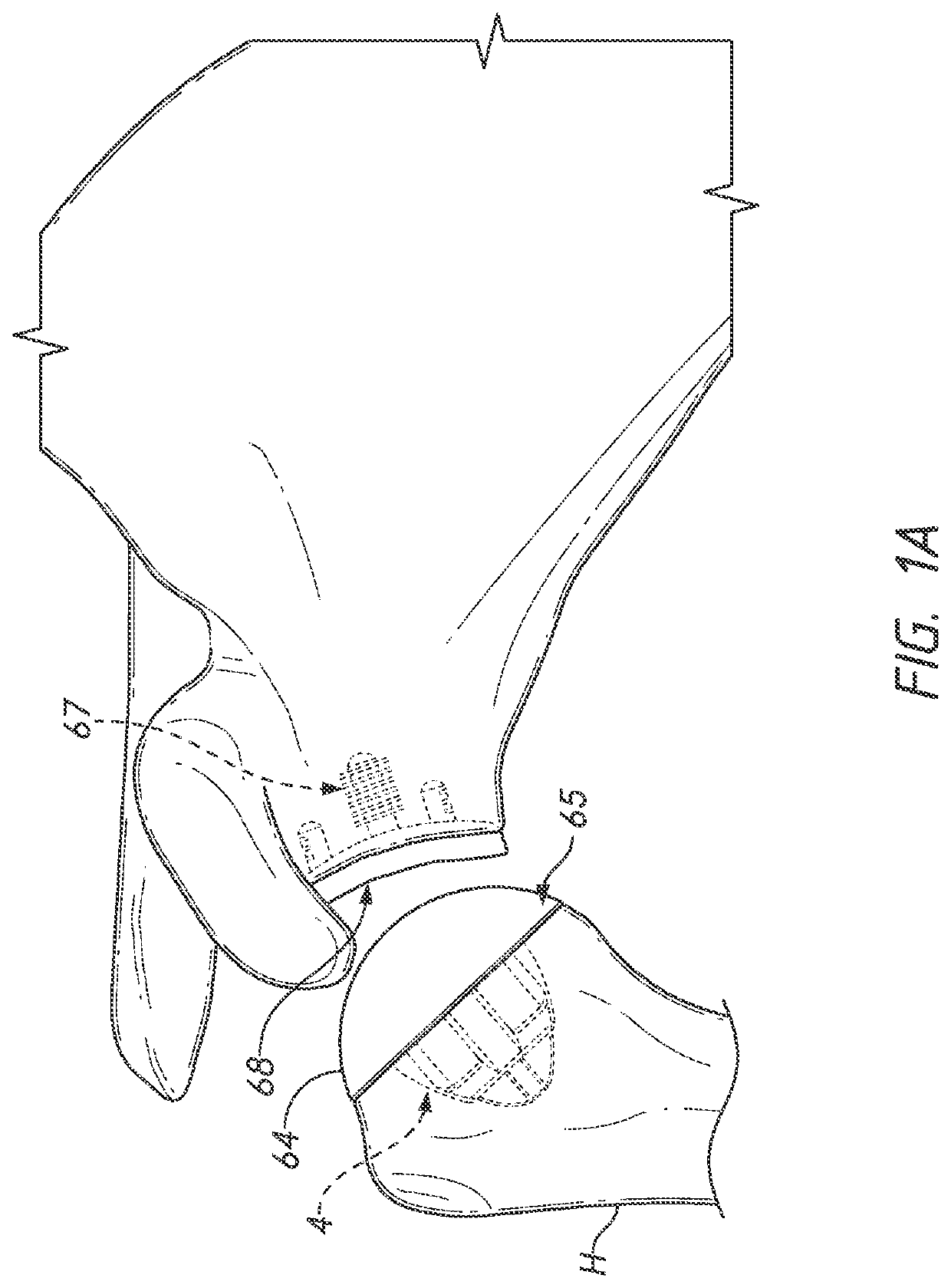
[0093]FIGS. 1A and 1B show two conventional approaches to total shoulder arthroplasty. FIG. 1A shows an anatomic approach in which the humeral head is replaced with an articular body 64 having an convex articular surface 65. The glenoid of the scapula can be modified with an implant 67 providing a concave surface 68 for articulation of the humeral articular body 64 The humeral articular body 64 is secured to the humerus H using a stemless anchor 4 that is dedicated for and only compatible with the anatomic articular body 64.

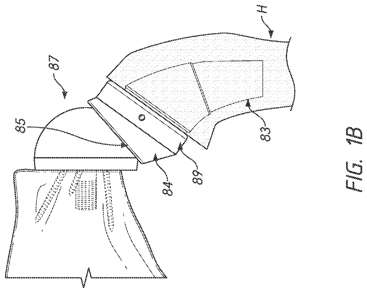
[0094]FIG. 1B shows a reverse approach in which the humerus H is fitted with an articular body 84 having a concave articular surface 85. The glenoid region of the scapula is fitted with a spherical articular body, commonly called a glenosphere 87. In this case, the concave articular surface 85 placed on the humerus articulates of the glenosphere 87, which is fixed relative to the scapula. The reverse articular body 84 is mounted to a tray 88 that is disposed betw...


PUM


Abstract

Various embodiments disclosed herein relate to stemmed and stemless humeral anchors for use in shoulder arthroplasty procedures. For example, the humeral anchor can include a first end, a second end, and an interior surface extending between the first end and the second end. The interior surface can be disposed about a recess disposed between the first end and the second end. The recess can be configured to secure a coupling of a shoulder articular body directly to the interior surface.

Description

[0001]This application claims priority to U.S. Provisional Application No. 62 / 740333, filed Oct. 2, 2018, the entire disclosure of which is incorporated herein by this reference thereto.BACKGROUNDField[0002]The present application relates to apparatuses and methods for reverse and anatomic shoulder prostheses.Description of the Related Art[0003]Arthroplasty is the standard of care for the treatment of shoulder joint arthritis. A typical anatomical shoulder joint replacement attempts to mimic anatomic conditions. For example, a metallic humeral stem and a humeral head replacement are attached to the humerus of the arm and replace the humeral side of the arthritic shoulder joint. Such humeral head replacement can articulate with the native glenoid socket or with an opposing glenoid resurfacing device.[0004]For more severe cases of shoulder arthritis, the standard treatment is a reverse reconstruction, which includes reversing the kinematics of the shoulder joint. A reverse shoulder pr...

Claims


Application Information

Patent Timeline
Patent Type & Authority Applications(United States)
IPC IPC(8): A61F2/40A61F2/30
CPCA61F2/4003A61F2/4014A61F2/30749A61F2/30771A61F2002/30224A61F2002/30884A61F2002/30383A61F2002/30607A61F2002/30011A61F2002/4022A61F2002/4085A61F2002/30428A61F2002/30495
Inventor GARGAC, SHAWN M.MUTCHLER, AUSTIN WYATTSTUMP, DAVID R.WOLFE, ALEXANDER PAUL
Owner HOWMEDICA OSTEONICS CORP
Why Eureka
Try Eureka