Mounting device and base station antenna system and mounting method

a technology of mounting device and antenna system, which is applied in the direction of antenna details, electrical apparatus, antennas, etc., can solve the problems of difficult mounting of rru on the bsa, and achieve the effect of easy and accurate mounting of rru

Pending Publication Date: 2022-02-03
COMMSCOPE TECH LLC
View PDF5 Cites 0 Cited by
  • Summary
  • Abstract
  • Description
  • Claims
  • Application Information

AI Technical Summary

Benefits of technology

[0004]An object of the disclosure is to provide a mounting device and a mounting method for mounting a RRU to a BSA and to provide a BSA system formed by means of the mounting device, wherein the mounting device may realize easy and accurate mounting of the RRU to the BSA.

Problems solved by technology

However, the mounting of the RRU on the BSA may be difficult.

Method used


Image

  • Mounting device and base station antenna system and mounting method
  • Mounting device and base station antenna system and mounting method
  • Mounting device and base station antenna system and mounting method

Examples


Embodiment Construction

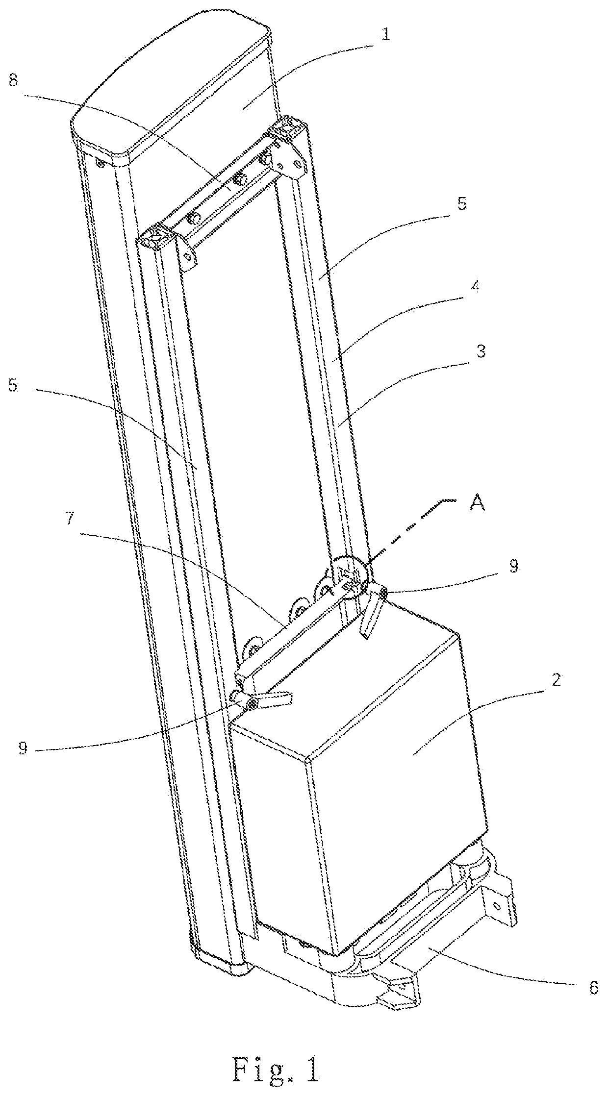
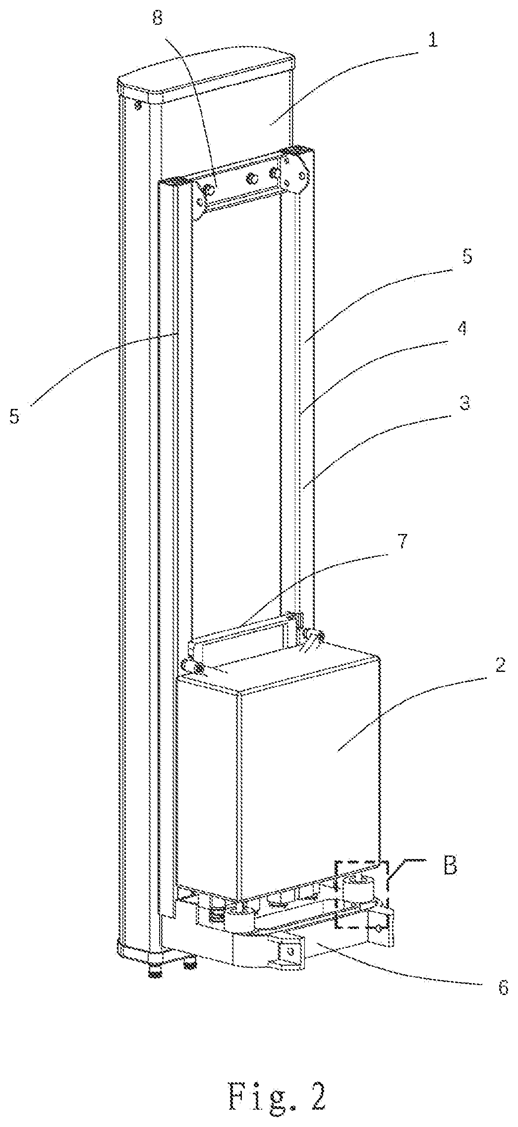
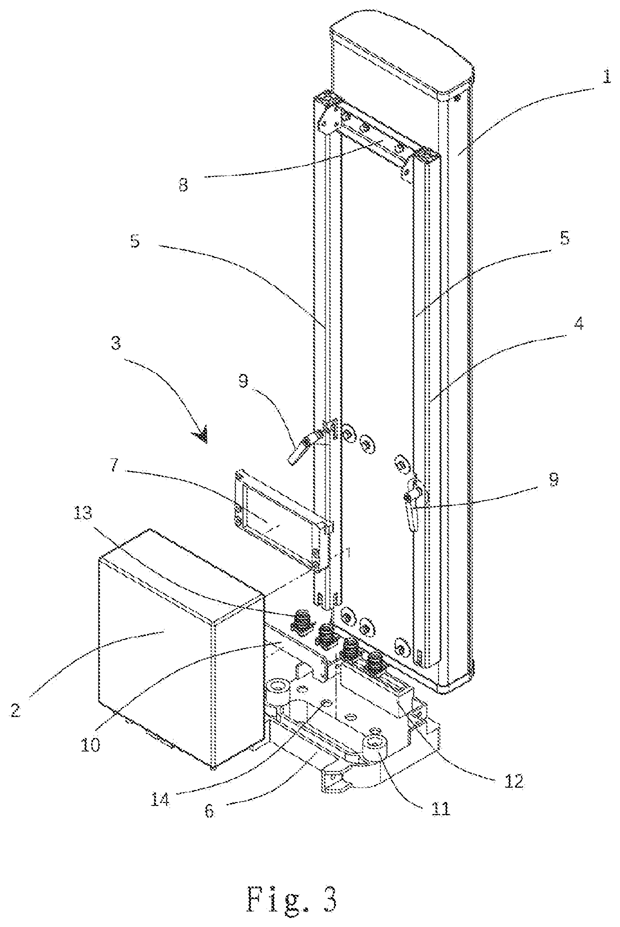
[0063]FIG. 1 and FIG. 2 are perspective views of a BSA system according to an embodiment of the invention in different positions of a RRU, and FIG. 3 is an exploded view of the BSA system of FIG. 1. The BSA system includes a BSA 1 and the RRU 2, wherein the RRU 2 may be mounted to the BSA 1 by means of a mounting device 3.

[0064]The mounting device 3 may include a support base 6 configured to be mounted to the BSA 1 and to support the RRU 2. In a lowered state shown in FIG. 1, the RRU 2 is supported on the support base 6, i.e. in a second position. In a raised state shown in FIG. 2, the RRU 2 is lifted from the support base 6, i.e. in a first position. In an unlocked state, the RRU 2 can move between the first position and the second position, for example, it can move linearly in a longitudinal direction of the BSA 1.

[0065]The mounting device 3 may include a support element 10 (see FIG. 3 and FIGS. 6A, 6B) configured to be mounted to the RRU 2 and movable together with the RRU 2 betw...


PUM


Abstract

The invention relates to a mounting device for mounting a remote radio unit (2) to a base station antenna (1) and relates to a base station antenna system formed thereby. The mounting device includes a support base (6) configured to be mounted to the base station antenna and to support the remote radio unit; a support element configured to be mounted to the remote radio unit and movable together with the remote radio unit between a first position, in which the support element is lifted from the support base, and a second position, in which the support element is supported on the support base; a plug arrangement including a plug element and a socket element, one of which is configured to be mounted to the base station antenna, and the other of which is configured to be mounted to the remote radio unit, wherein in the first position, the plug element and the socket element are separated from each other, and in the second position, the plug element and the socket element are engaged with each other.

Description

RELATED APPLICATION[0001]The present application claims priority from and the benefit of Chinese Patent Application No. 202010740945.2, filed Jul. 29, 2020, the disclosure of which is hereby incorporated herein by reference in full.FIELD OF THE INVENTION[0002]The disclosure relates to the field of base station antennas, and more particularly, relates to a mounting device and a mounting method for mounting a remote radio unit (RRU) to a base station antenna (BSA), and relates to a base station antenna system.BACKGROUND OF THE INVENTION[0003]In a wireless communication network, a BSA may be provided with a RRU, and they may be electrically connected with each other through jumper lines. Typically, a BSA and a RRU may be separately mounted on different poles, so both the BSA and the RRU need separate mounting spaces. A relative position of the BSA and the RRU may only be determined at a mounting location, so a length of the jumper lines for electrically connecting the BSA and the RRU m...

Claims


Application Information

Patent Timeline
Patent Type & Authority Applications(United States)
IPC IPC(8): H01Q1/12H01Q1/24
CPCH01Q1/1228H01Q1/246H01Q1/12H01Q1/1207H01Q1/24
Inventor LIU, MAOSHENGTANG, PULIANGLIU, ZHAOHUISU, RUIXIN
Owner COMMSCOPE TECH LLC
Why Eureka
Try Eureka