Metal framing member with off site manufactured locking tabs

a technology of metal framing members and locking tabs, which is applied in the direction of girders, walls, joists, etc., can solve the problems of inaccurate and effective bending by the installer, limited use, cost and difficulty, etc., and achieve the effect of secure and quick

Inactive Publication Date: 2005-08-04
INT BUILDING SYST
View PDF13 Cites 16 Cited by
  • Summary
  • Abstract
  • Description
  • Claims
  • Application Information

AI Technical Summary

Benefits of technology

[0008] The present invention is a metal framing member including at least one manufactured locking tab. The framing member has a substantially rectangular cross-section. Preferentially, at least two stiffeners run longitudinally along the metal framing member. Two locking tabs are punched out of the bottom portion between the two stiffeners. The locking tabs resulting from the punched out section of the framing member have an angled locking guide which serves to assist the locking tabs to be mated to corresponding punched out tab openings in a slotted tab punched out of a track meant to be attached to said framing member. Once the framing member locking tab is slid over its mating slotted tab so that tab openings are aligned with the locking tabs, the framing member is locked into place along the track. Additional locking tabs are optionally provided on each leg of the framing member to enable the framing member to be more securely attached to the track member. The tab openings that engage by locking tabs on the framing member can be either round or rectangular. Also, rather than provide another tab arrangement on the legs of the framing member, an opening that matches a mating opening in the track member can be pinned together using press pins well known in the art. Each locking tab assembly on the framing member and its corresponding track member is made at the factory using computer software to accurately match each position in accordance with the building design. Thus, the two parts can be put together securely and quickly without the use of screws, bolts or other fasteners.

Problems solved by technology

However, its use is limited due to high cost, erection problems, and handling difficulties.
Introducing this chase after the framing member has been fabricated, as well as clipping or attaching the wiring to the member, can be tedious and time consuming.
The patent mentioned above does not address this concern.
The use of the STRONG STUD taught in the '804 patent which utilizes heavy gauge, high strength material would make accurate and effective bending by the installer costly and difficult.
Further, manual bending for even heavier gauge material that might be necessary in certain construction environments would be impossible.
However, the Madsen et al. knock-out opening is substantially greater than the size of the tab which weakens the stud and potentially can cause buckling or torsion problems.
Nor does Madsen et al. disclose or suggest the use of pre-punched pilot holes but instead relies solely on the use of self-tapping screws to connect the tab to another structure.

Method used


Image

  • Metal framing member with off site manufactured locking tabs
  • Metal framing member with off site manufactured locking tabs
  • Metal framing member with off site manufactured locking tabs

Examples


Embodiment Construction

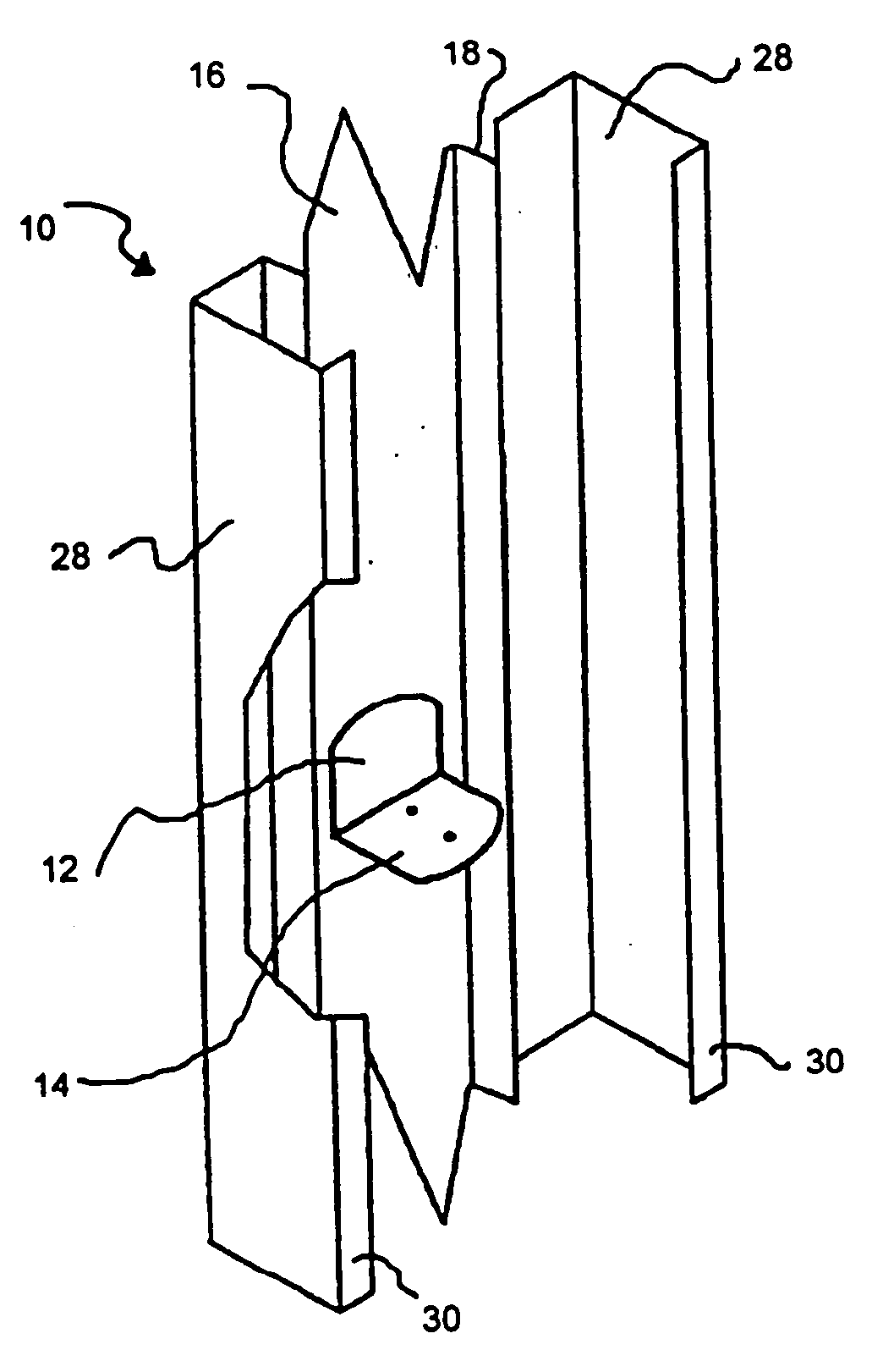
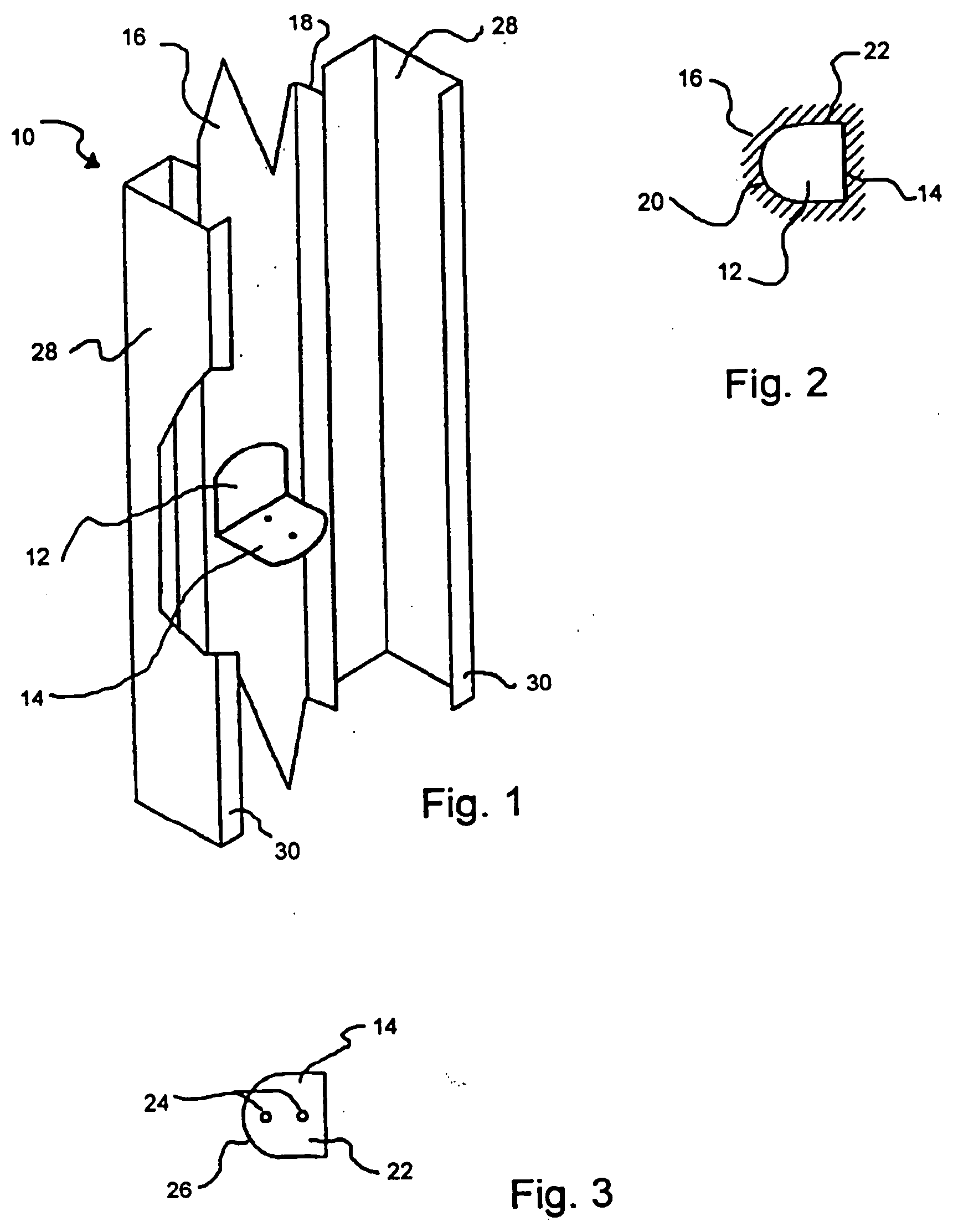
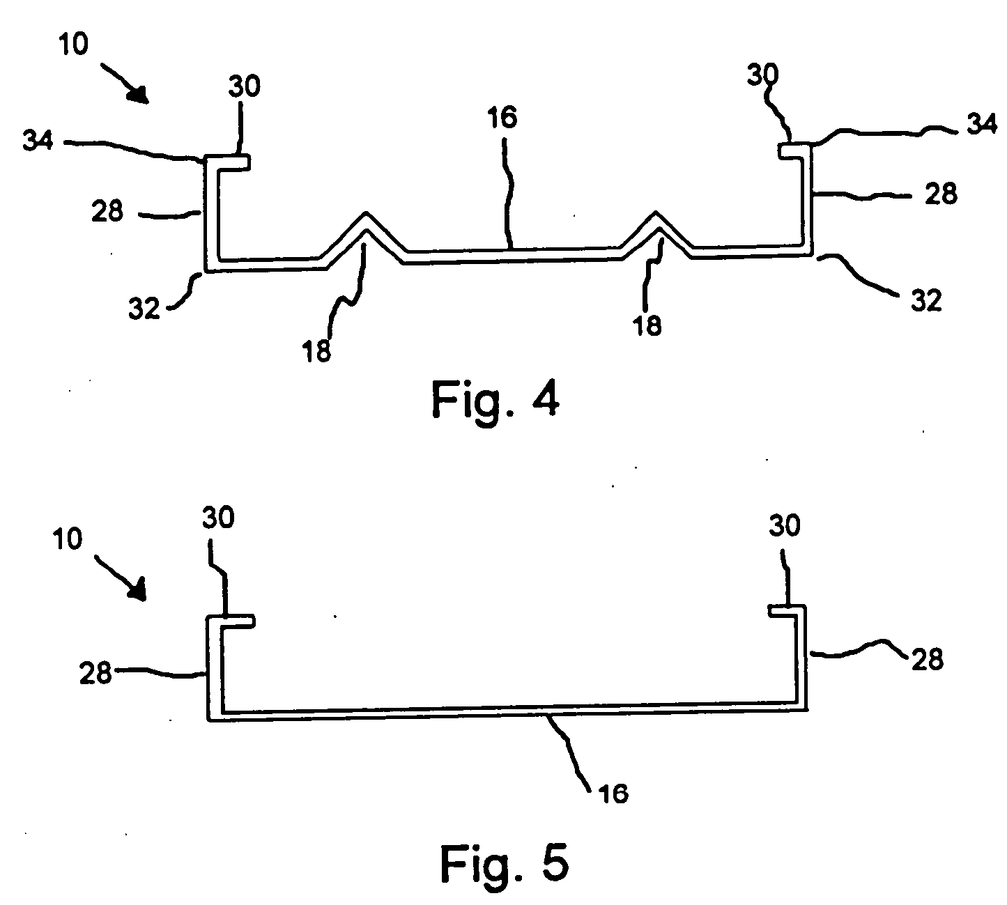
[0041]FIG. 1 illustrates metal framing member 10 with knock out opening 12 and tab 14. While tab 14 is usually made so that tab 14 is approximately 90 degrees with surface 16, since tab 14 is made at the factory using computer assisted machinery, any precise angle may be selected. (See, e.g. FIG. 13) Tab 14 and its corresponding knock out opening 12 are preferably located centrally in surface 16, which runs the length of framing member 10. However, since the stud is manufactured to the design specifications necessary to ensure precision and ease of fastening, other positions can be easily selected. In fact, different locations on surface 16 as well as different tab angles could be provided in each framing member if desired.

[0042] Surface section 16 is generally 6″ to 8″ wide. In the preferred embodiment, surface section 16 includes stiffeners 18, which run longitudinally along surface section 16. Typically, as noted above, knock out opening 12 is centrally located between stiffener...


PUM


Abstract

A metal framing member for use as a stud, joist, rafter, truss, etc. is disclosed. The framing member includes at least one knock out opening and a corresponding tab that is positioned onto the metal framing member during the manufacturing process via computer so that structures built using the studs such as window frames, door jams, etc. are accurately and quickly fabricated. The knock out opening can also be used as a chase to allow wiring or a stiffening rod to pass through the member. Each tab is also preferably provided with a pair of pre-punched holes so that the tab can be fastened to other building components using standard screws.

Description

[0001] This application is a continuation-in-part of U.S. patent application Ser. No. 10 / 459,868, filed Jun. 12, 2003, which was a continuation-in-part of 09 / 885,843, filed on Jun. 20, 2001, now abandoned.FIELD OF THE INVENTION [0002] This invention relates to dwelling framing members, and in particular, to an attachment locking tab and opening which is used to attach one stud to another in such members by having the tab and its corresponding knock out positioned onto the metal stud via computer in accordance with the layout plans of the structure that is to be formed. BACKGROUND OF THE INVENTION [0003] Structural members are frequently made of metal, as it has advantages over wooden structural members. Compared to wood, metal is insect proof, fire proof, and has high uniformity and strength. However, its use is limited due to high cost, erection problems, and handling difficulties. U.S. Pat. No. 5,315,804, issued to Attalla, addresses some of these concerns. The patent discloses an...

Claims


Application Information

Patent Timeline
Patent Type & Authority Applications(United States)
IPC IPC(8): E04B2/74E04B2/78E04C3/04E04C3/07
CPCE04B2/7457E04B2/767E04B2/789E04B2002/7488E04C3/07E04C2003/0491E04C3/32E04C2003/0421E04C2003/0434E04C2003/0473E04C3/11
Inventor ATTALLA, ANTHONY P.
Owner INT BUILDING SYST
Why Eureka
Try Eureka