
Metal framing member with off site manufactured locking tabs
a technology of metal framing members and locking tabs, which is applied in the direction of girders, walls, joists, etc., can solve the problems of inaccurate and effective bending by the installer, limited use, cost and difficulty, etc., and achieve the effect of secure and quick
- Summary
- Abstract
- Description
- Claims
- Application Information
AI Technical Summary
Benefits of technology
Problems solved by technology
Method used
Image

Examples
Embodiment Construction
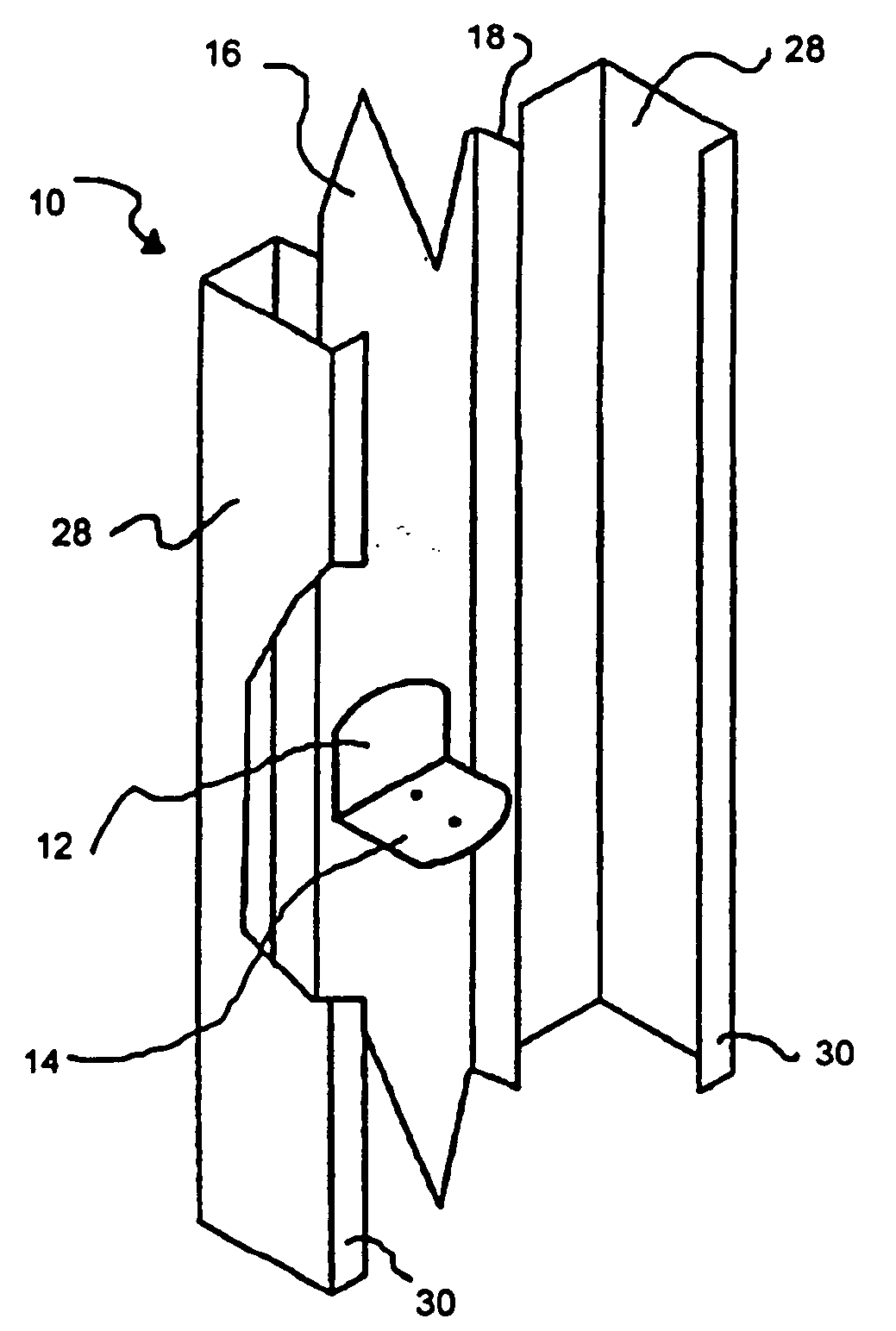
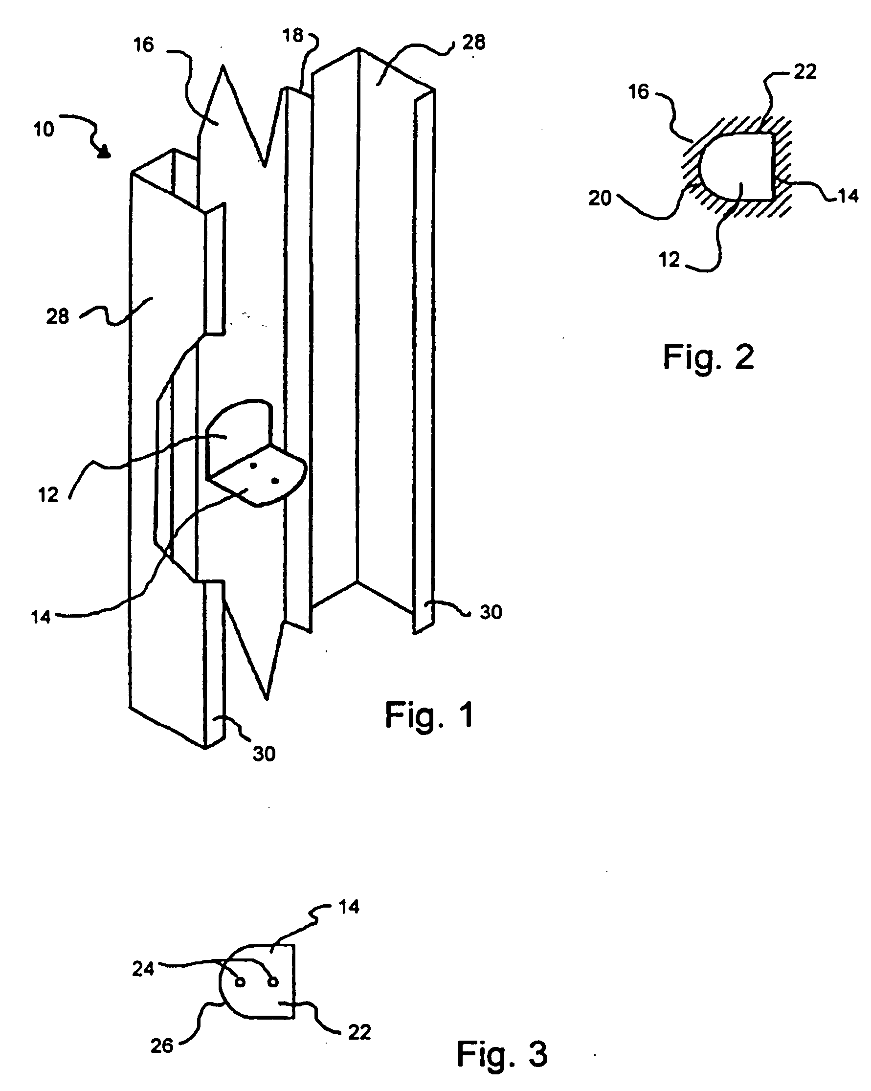
[0059]FIG. 1 illustrates metal framing member 10 with knock out opening 12 and tab 14. While tab 14 is usually made so that tab 14 is approximately 90 degrees with surface 16, since tab 14 is made at the factory using computer assisted machinery, any precise angle may be selected. (See, e.g. FIG. 13) Tab 14 and its corresponding knock out opening 12 are preferably located centrally in surface 16, which runs the length of framing member 10. However, since the stud is manufactured to the design specifications necessary to ensure precision and ease of fastening, other positions can be easily selected. In fact, different locations on surface 16 as well as different tab angles could be provided in each framing member if desired.
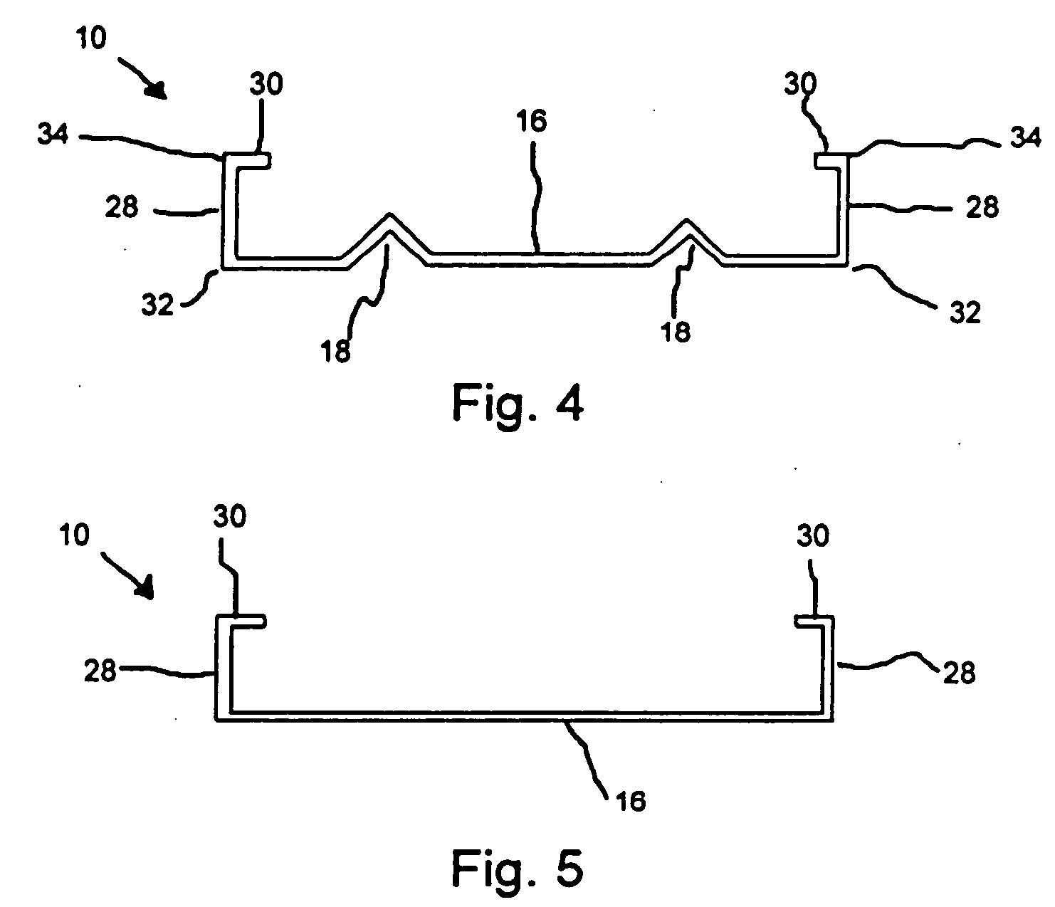
[0060] Surface section 16 is generally 6″ to 8″ wide. In the preferred embodiment, surface section 16 includes stiffeners 18, which run longitudinally along surface section 16. Typically, as noted above, knock out opening 12 is centrally located between stiffener...
PUM
 Abstract
Description
Claims
Application Information