Mount for a firearm

a mount and firearm technology, applied in the field of firearms, can solve the problems of mounting adapter devices being more likely to snag undesirably on items in the environmen

Active Publication Date: 2022-02-10
ZRODELTA LLC
View PDF0 Cites 1 Cited by
  • Summary
  • Abstract
  • Description
  • Claims
  • Application Information

AI Technical Summary

Benefits of technology

The invention described in this patent has the drawback of requiring a protruding knob, which makes it easier for the device to get stuck on other objects.

Problems solved by technology

The '307 patent has the disadvantage of requiring a knob that protrudes substantially from the main body to provide space for the compressed spring received around the push rod.
This requirement makes the mount adapter device more likely to snag undesirably on items in the environment.

Method used


Image

  • Mount for a firearm
  • Mount for a firearm
  • Mount for a firearm

Examples


Embodiment Construction

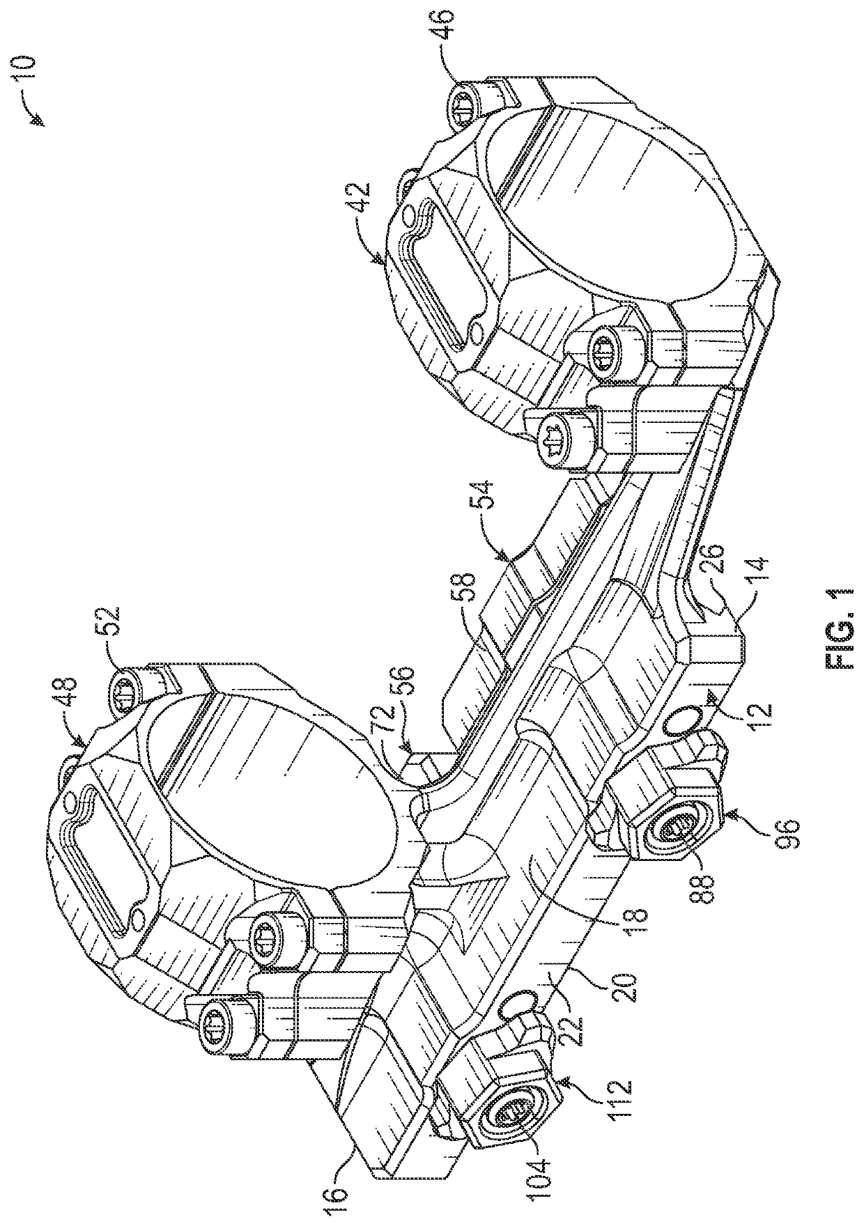
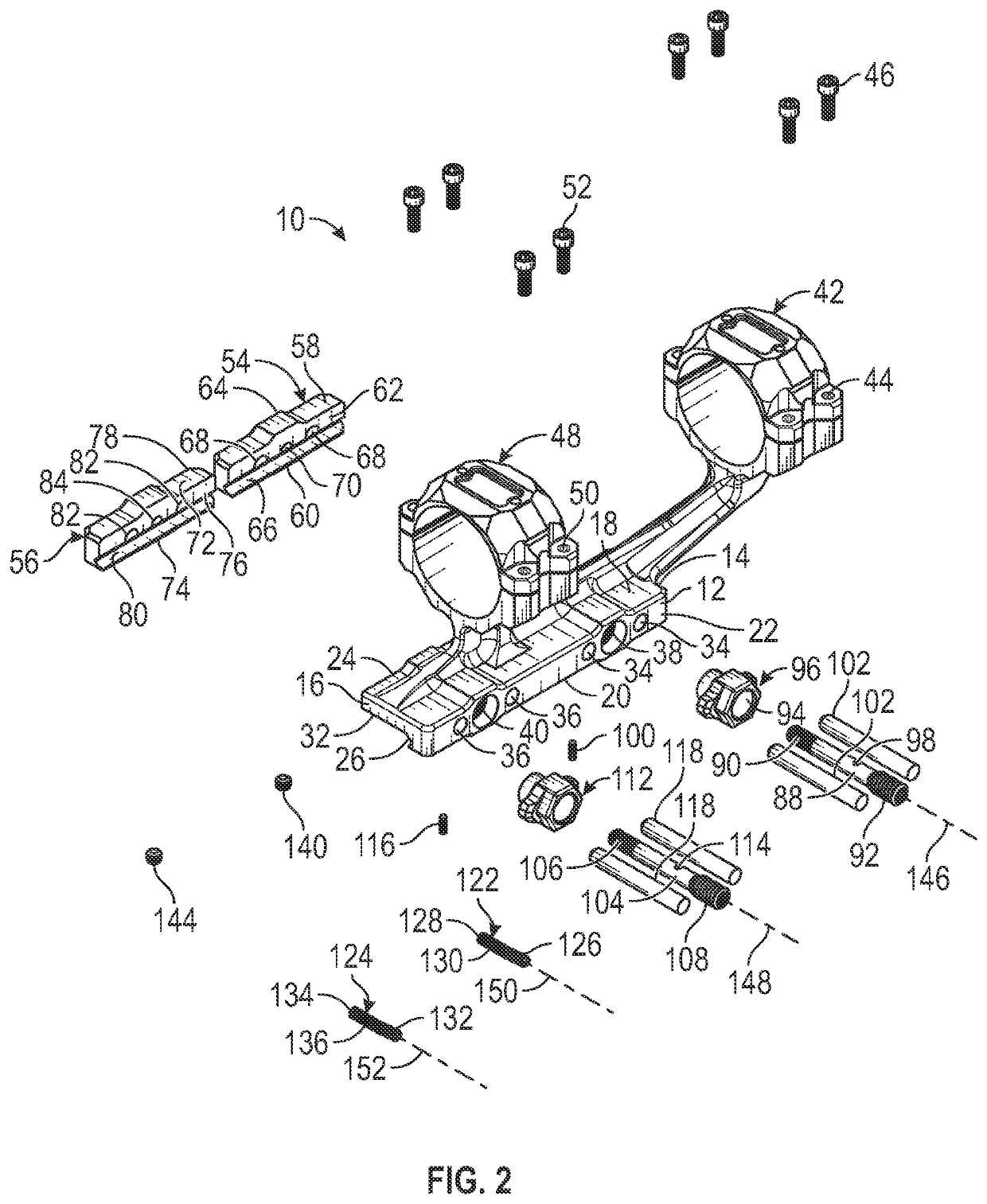
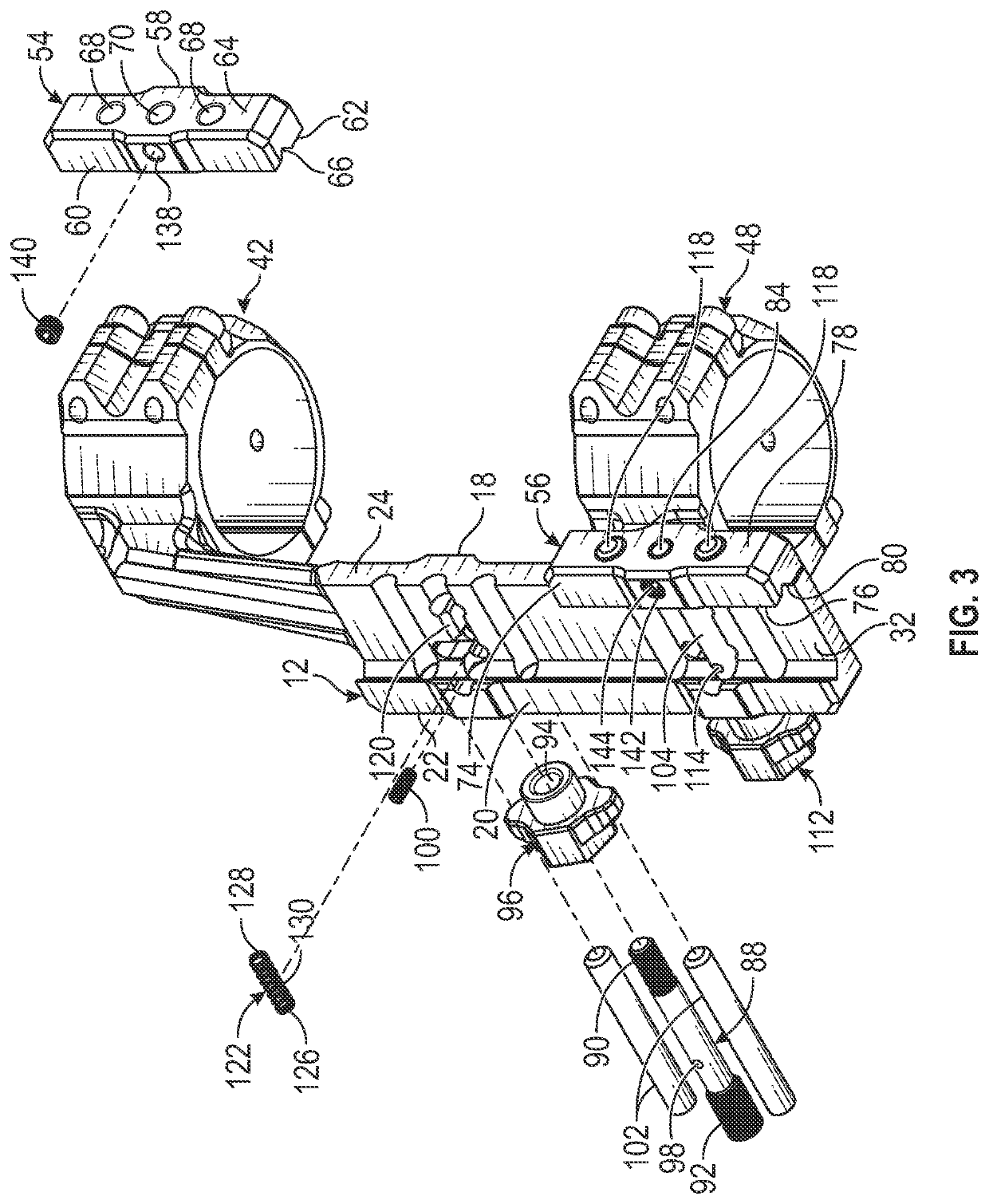
[0016]An embodiment of the mount for a firearm of the present invention is shown and generally designated by the reference numeral 10.

[0017]FIGS. 1-3 illustrate the improved mount for a firearm 10 of the present invention. More particularly, the mount for a firearm has a body 12 having a front 14, rear 16, top 18, bottom 20, right side 22, and left side 24. The bottom right side of the body forms a first clamp 26 configured to engage a first edge 28 of a mounting rail 86 having opposed lateral edges (second edge 30 opposes the first edge). The mounting rail is depicted in FIGS. 4 and 5 and is shown in more detail in FIGS. 2 and 3 of the '307 patent discussed previously. The body defines a downward facing surface 32 configured to face an upper surface of the mounting rail. The right side of the body defines two pairs of guide pin apertures 34, 36 positioned on either side of two pushrod apertures 38, 40. The top front of the body has an attached front scope ring 42. The front scope r...


PUM


Abstract

A mount for a firearm has a body having a first clamp configured to engage a first edge of the rail, a jaw movably connected to the body and having a second clamp opposed to the first clamp and operable with the respective clamps to engage respective opposed lateral edges of the rail, a spring biasing the jaw toward the body, and at least a portion of the spring being between the clamps. There may be a pushrod connected to a first one of the body and the jaw and slidably received by the other of the body and the jaw. The spring may be laterally positioned to one side of the pushrod. The spring may be a coil spring having a spring axis offset from a pushrod axis defined by the pushrod.

Description

CROSS-REFERENCE TO RELATED APPLICATION[0001]This application claims the benefit of U.S. Provisional Patent Application No. 63 / 063,412 filed on Aug. 9, 2020, entitled “Universal Fire Control, Rechargeable, Global Positioning and Alert Communication, Mount Adapter Utilizing Push System with Offset Springs, Mid-Receiver Carbine, and Ambi-Magazine Release,” which is hereby incorporated by reference in its entirety for all that is taught and disclosed therein.FIELD OF THE INVENTION[0002]The present invention relates to firearms, and more particularly to a mount for a firearm that enables the mount to be easily attached to and detached from a firearm.BACKGROUND AND SUMMARY OF THE INVENTION[0003]Many designs exist for mounting accessories to universal weapon accessory rails such as the NATO STANAG 4694 accessory rail. Methods of attachment include screws, levers, and knobs. One example of a prior art of such a design is the mount adapter device utilizing a push system disclosed in U.S. Pat...

Claims


Application Information

Patent Timeline
IPC IPC(8): F41G11/00
CPCF41G11/003F41A19/15F41A19/43F41A19/14F41A17/38
Inventor RALEY, TIMOTHY WAYNEMCGINTY, AARON A.
Owner ZRODELTA LLC
Why Eureka
Try Eureka