Apparatus with Variable Pitch and Continuous Tilt for Rotors on an Unmanned Fixed Wing Aircraft

Pending Publication Date: 2022-04-14
IERUS TECH
9 Cites 0 Cited by

AI-Extracted Technical Summary

Problems solved by technology

Rotary wing UAVs offer the ability to hover and take-off and land vertically (VTOL) but are known to have less efficiency and speed than the fixed wing UAVs.
Fixed wing UAVs have been used widely because of their simple design, high endurance, high range and high-speed capability, but these are incapable of VTOL.
However, current aircraft configurations that are...

Benefits of technology

[0012]A continuous tilt mechanism allows for the continuous tilt of forward flight propulsion motors, from a position optimized for the VTOL and/or hover of an aircraft, to a position optimized for forward flight of an aircraft. This continuous tilt mechanism allows the entire propulsion system, including the variable pitch rotor mechanism, to be rotated around an axis so that the thrust vector of the propulsion system may be oriented in whatever direction is optimal for any given flight conditions. The axis of rotation of the continuous tilt mechanism produces a thrust vector of the propulsion system to create a pitching moment that will force the continuous tilt mechanism to rotate into the forward flight orientation.
[0013]The variable pitch of the mechanism allows the aircraft to optimize rotor blade pitch for maximum efficiency in both the VTOL, hover, and forward flight operating regimes. The continuous tilt of the mechanism allows the aircraft to transition smoothly from VTOL and hover to forward flight, while providing adequate yaw control authority below the minimum maneuvering airspeed of the aircraft in forward flight.
[0014]The apparatus of the pr...

Abstract

An apparatus providing continuous tilt and variable pitch for rotors on a fixed wing VTOL aircraft. An actuator on a housing rotates a first pivot point on a motor mount to tilt a motor to horizontal and vertical positions. Simultaneously, an actuator on the motor mount rotates a fork on a second pivot point on the motor mount to adjust the pitch of the rotors attached to a free end of the motor's drive shaft. A lower swash plate on the drive shaft is attached to the fork. An upper swash plate on the drive shaft is attached to the rotors. The swash plates are attached to each other with a shaft bushing attached to a shaft ball bearing. The shaft bushing allows both swash plates to move linearly along the shaft when the fork is rotated. The shaft ball bearing allows the upper swash plate to rotate with the drive shaft while the lower swash plate remains stationary.

Application Domain

Technology Topic

Image

  • Apparatus with Variable Pitch and Continuous Tilt for Rotors on an Unmanned Fixed Wing Aircraft
  • Apparatus with Variable Pitch and Continuous Tilt for Rotors on an Unmanned Fixed Wing Aircraft
  • Apparatus with Variable Pitch and Continuous Tilt for Rotors on an Unmanned Fixed Wing Aircraft

Examples

  • Experimental program(1)

Example

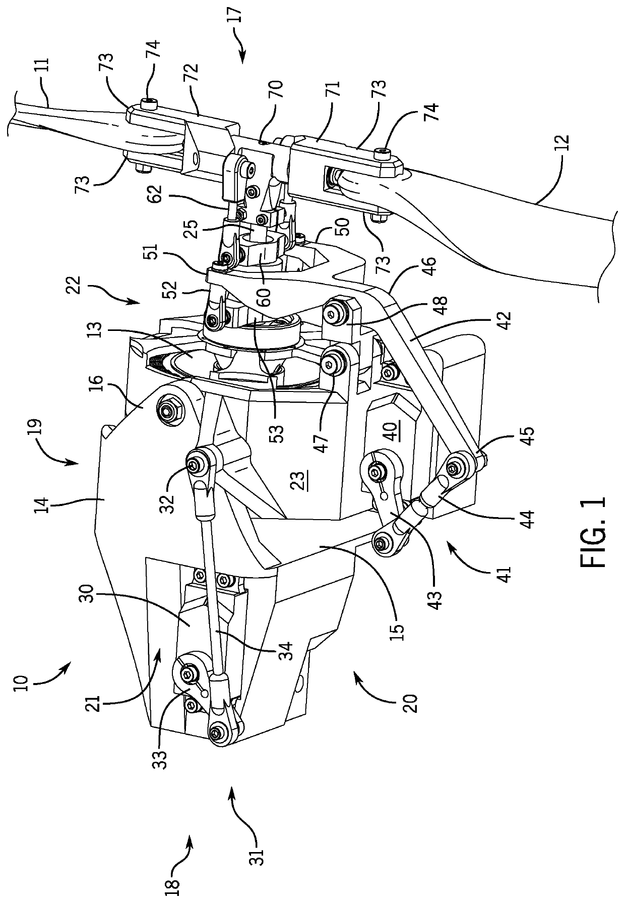
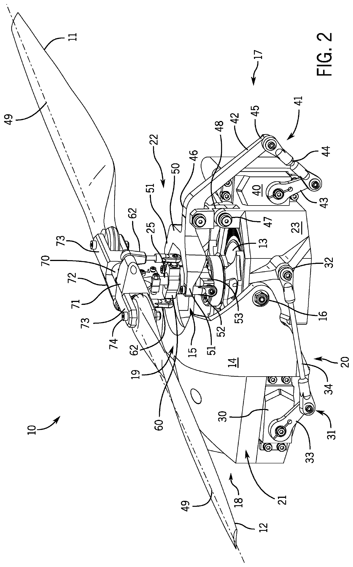
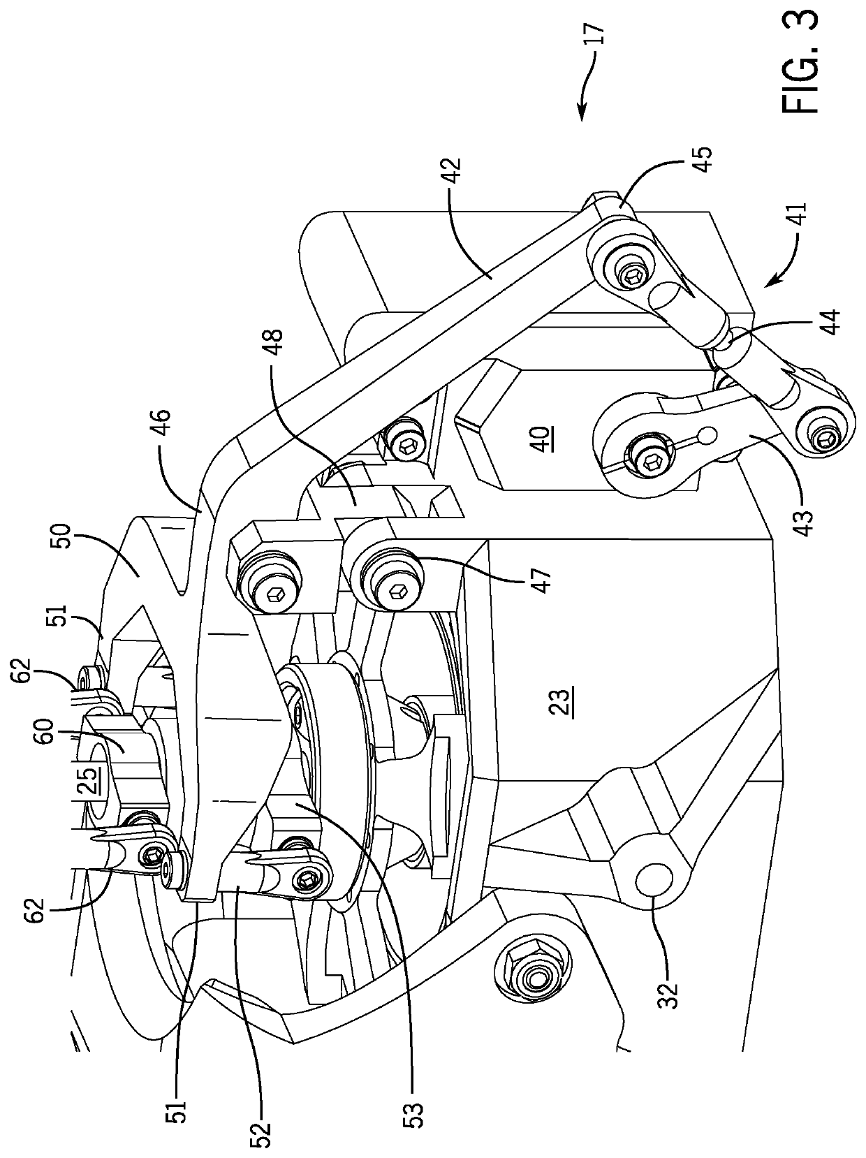
[0022]While the following description details the preferred embodiments of the present invention, it is to be understood that the invention is not limited in its application to the details of arrangement of the parts or steps of the methods illustrated in the accompanying figures, since the invention is capable of other embodiments and of being practiced in various ways.
[0023]There usually must be a compromise between the pitch of the rotors necessary to perform vertical takeoff and landing and the pitch necessary for efficient forward flight. Some designers of VTOL UAVs have developed tilt-rotor designs that have continuous tilt functionality, but without the ability to vary pitch in flight they must settle for rotors with pitch that is neither optimized for hover or for forward flight. This lack of optimization can lead to dangerous situations when landing an aircraft, due to the compromised function of the rotors, such as rotor stall due to an excessive rate of decreasing altitude. Other designers of fixed wing VTOL UAVs have previously used separate propulsion systems for the VTOL phases of operation and the forward flight phase. Separate propulsion systems result in a heavier and less optimized system than can be achieved by the continuous tile and variable pitch mechanisms of the present invention.
[0024]FIG. 1 shows a front, left, and bottom perspective view of an apparatus 10 for providing variable pitch and continuous tilt for rotors 11 and 12, with a motor 13 and the rotors 11 and 12 in a forward flight configuration. Apparatus 10 has a housing 14 with an open interior 15 and a pair of motor mount support members 16. The housing has a front end 17, a rear end 18, a top 19, a bottom 20, a left side 21 and a right side 22. A motor mount 23 is attached rotatably to the motor mount support members 16 on the left side 21 and the right side 22 of the housing 14. The motor mount 23 has an open interior 24 (see FIG. 6). The motor 13 is attached to the motor mount 23 in the interior 24 of the motor mount 23. The motor has a drive shaft 25 with rotors 11 and 12 attached to a free end of the drive shaft 25.
[0025]A rotor tilt adjustment actuator 30 is attached to the housing 14 near the rear end 18, bottom 20, and left side 21 of the housing 14. The rotor tilt adjustment actuator 30 is connected with a motor title linkage 31 to a first pivot point 32 on the left side of the motor mount 23. The motor tilt linkage 31 comprises a servo drive arm 33 connected rotatably to a first end of a connecting rod 34. A second opposite end of the connecting rod 34 is connected rotatably the first pivot point 32 on a left side of the motor mount 23. The rotor tilt adjustment actuator 30 tilts the motor mount 23 from a horizontal position to a vertical position and vice versa as the motor mount 23 is rotated on the motor mount support members 16 by the rotor tilt adjustment actuator 30, pushing or pulling the first pivot point 32 on the motor mount 23.
[0026]A rotor pitch adjustment actuator 40 is attached to the motor mount 23 at the right side of the motor mount 23. The rotor pitch adjustment actuator 40 is connected with rotor pitch linkage 41 to a rotor pitch adjustment fork 42. The rotor pitch linkage 41 comprises a servo drive arm 43 connected rotatably to a first end of a connecting rod 44. A second opposite end of the connecting rod 44 is connected rotatably to a first end 45 of the rotor pitch adjustment fork 42. The rotor pitch adjustment fork 42 is attached rotatably at its second opposite end 46 to a second pivot point 47 on the motor mount 23. The rotor pitch adjustment actuator 40 adjusts the pitch of the rotors 11 and 12 by rotating the rotor pitch adjustment fork 42 on the second pivot point 47.
[0027]The second pivot point 47 may be connected to the second opposite end 46 of the rotor pitch adjustment fork 42 with a dual pivot linkage 48. The rotor pitch adjustment fork 42 then rotates on the dual pivot linkage 48 and the dual pivot linkage 48 rotates on the second pivot point 47.
[0028]A fork member 50 is attached to the rotor pitch adjustment fork 42 at the second opposite end 46. The fork member comprises a pair of spaced apart tines 51. A first connecting member 52 is attached to each tine 51 and each tine 51 extends towards the front of the motor mount 23 and attaches to a lower swash plate 53. The lower swash plate 53 is attached slideably to the drive shaft 25, with the drive shaft 25 passing through an interior 54 of the lower swash plate 53 (see FIG. 4).
[0029]An upper swash plate 60 is attached rotatably to the lower swash plate 53 with the drive shaft 25 passing through an interior 61 (see FIG. 4) of the lower swash plate 53. A second connecting member 62 is attached to each side of the upper swash plate 60. Each second connecting member 62 extends and connects to a respective rotor holders 71 and 72. The rotation of the rotor pitch adjustment fork 42 imparts a force on the first connecting members 52, causing the upper swash plate 60 to translate linearly along the drive shaft 25 due to the dual-pivot linkage 48. The dual-pivot linkage 48 is critical to the function of the variable pitch mechanism as without it, the movement of the fork member 50 would transcribe an arc and would not be able to move the swash plates 53 and 60 linearly along the drive shaft 25.
[0030]Each rotor holder 71 and 72 is attached rotatably to a rotor head hub 70. The rotor head hub 70 is attached to the free end of the drive shaft 25. Each rotor 11 and 12 is attached to a respective rotor holder 71 and 72. Each rotor holder 71 and 72 has spaced apart connecting members 73 which connect the rotors 11 and 12 to the respective rotor holders 71 and 72 with bolts 74.
[0031]FIG. 2 shows a front, left, top perspective view of the apparatus 10, with the motor 13 and the rotors 11 and 12 in a configuration for hovering, take-off, and landing. The motor mount 23 is tilted upward by action of the rotor tilt adjustment actuator 30 which pushes the connecting rod 34 forward. Pushing the connecting rod 34 forward pushes the first pivot point 32 upwards, thereby rotating the motor mount 23, the motor 13, and the rotors 11 and 12 upward. The motor mount 13 is titled downward by the rotor tilt adjustment actuator 30 pulling the first pivot point 32 downward, placing the motor 13 and rotors 11 and 12 in an orientation for forward flight.
[0032]FIG. 3 is an enlarged view of the rotor pitch adjustment fork 42, the fork member 50, the lower swash plate 53, and the upper swash plate 53, as shown in FIG. 2.
[0033]FIG. 4 is a sectional view through the center of the lower swash plate 53, the upper swash plate 60, and the drive shaft 25. FIG. 4 illustrates the features that connect the lower swash plate 53 to the upper swash plate 60, allow the upper swash plate 60 to rotate with the drive shaft 25 while the lower swash plate 53 does not rotate with the drive shaft 25, and allows the lower swash plate 53 and the upper swash plate 60 to slide towards and away from the rotor holders 71 and 72.
[0034]The lower swash plate 53 has a ball bearing 63 positioned around the drive shaft 25. An outer wall 64 of the ball bearing 63 is attached to an inner wall 65 of the interior 54 of the lower swash plate 53, near a front end of the lower swash plate 53. The lower swash plate 53 has a thrust bearing 66 positioned slidably around the drive shaft 25 behind the ball bearing 63. The thrust bearing 66 is spaced apart from the inner wall 65 of the lower swash plate. A sleeve bushing 67 is inserted through the ball bearing 63 and is attached to an inner wall 68 of the ball bearing 63. The sleeve busing 67 is positioned slidably around the drive shaft 25 and is attached to the upper swash plate 60, thereby connecting the upper swash plate 60 rotatably to the lower swash plate 53. Preferably, a front end 80 of the sleeve busing 67 has a flange 81 which is connected to a shelf 82 in the interior 61 of the upper swash plate 60 and the sleeve bushing 67 is press fit into both the upper swash plate 60 and the ball bearing 63. The thrust bearing 66 provides the transfer of axial loads from the ball bearing 63 to the face of the lower swash plate 53 against which the thrust bearing 66 is seated. The thrust bearing 66 is fitted into the lower swash plate 53 with a loose fit, so that the outer diameter of the thrust bearing 66 does not rub the inner wall 65 of the lower swash plate 53. The ball bearing 63 prevents the movement of the thrust bearing 66 against which the ball bearing 63 is seated. This assembly of the lower swash plate 53 and the upper swash plate 60 allows the free rotation of the upper swash plate 60 with respect to the lower swash plate 53 and allows the loads imparted onto the upper swash plate 60 to be freely transferred to the lower swash plate 53 during high speed rotation of the drive shaft 25. The upper swash plate rotation is driven by the rotation of the rotor head hub 70. The rotation is transferred through the rotor holders 71 and 72 and the connecting members 62 to the upper swash plate 60.
[0035]FIG. 5 is an enlarged perspective view of the rotor head hub 70, the rotor holders 71 and 72, the connecting members 62, and the upper swash plate 60. FIG. 5 further shows that the rotor head hub 70 can be attached to the free end of the drive shaft 25 of the motor 13 with a clamp member 75.
[0036]FIG. 6 is a sectional front, right, top perspective view of apparatus 10. FIG. 6 further shows a feathering shaft 76 in the rotor head hub 70.
[0037]For forward flight, a signal from the rotor tilt adjustment actuator 30 causes the actuator drive arm 43 to rotate clockwise. The connecting rod 34 connected to the actuator drive arm 43 then pulls the motor mount 23 downward, so that the drive shaft 25 is in a horizontal orientation for forward flight. For vertical flight or hovering or landing, a signal from the rotor tilt adjustment actuator 30 causes the actuator drive arm 43 to rotate counterclockwise. The connecting rod 34 pushes the motor mount 23 upward so that the drive shaft 25 is in a vertical position. In this manner, the rotor tilt adjustment actuator 30 can position the drive shaft 25 at any angle from horizontal to vertical.
[0038]For adjusting the pitch of the rotors 11 and 12, a signal from the rotor pitch adjustment actuator 40 to rotate the rotors 11 and 12 around the longitudinal axis 49 (see FIG. 2) of the rotors 11 and 12 in a first direction causes the actuator drive arm 43 to rotate clockwise. The actuator drive arm 43 then pulls the connecting rod 44 downward which then pulls the first end and 45 of the rotor pitch adjustment fork 42 downward and the second opposite end 46 extends upward linearly. As the second opposite end 46 extends upward, the upper swash plate 60 is pushed upward along the drive shaft 25 of the motor 13 and the rotors 11 and 12 are rotated around their longitudinal axis 49 thereby adjusting pitch of the rotors 11 and 12 in a first direction.
[0039]A signal from the rotor pitch adjustment actuator 40 to rotate the rotors 11 and 12 around the longitudinal axis 49 of the rotors in a second opposite direction causes the actuator drive arm 43 to rotate counterclockwise. The actuator drive arm 43 then pushes the first end 45 of the rotor pitch adjustment fork 42 upward and the second opposite end 46 extends downward linearly. As the second opposite end 46 extends downward, the upper swash plate is pulled downward along the drive shaft 25 and the rotors are rotated around their longitudinal axes 49 thereby adjusting pitch of the rotors in a second opposite direction.
[0040]The tilt of the motor and rotors and the pitch of the rotors can be changed variably, simultaneously, and continuously as needed to maintain desired flight characteristics.
[0041]The foregoing description illustrates and describes the disclosure. Additionally, the disclosure shows and describes only the preferred embodiments but, as mentioned above, it is to be understood that the preferred embodiments are capable of being formed in various other combinations, modifications, and environments and are capable of changes or modifications within the scope of the invention concepts as expressed herein, commensurate with the above teachings and/or the skill or knowledge of the relevant art.
[0042]The embodiments described herein above are further intended to explain the best modes known by applicant and to enable others skilled in the art to utilize the disclosure in such, or other, embodiments and with the various modifications required by the particular applications or uses thereof. Accordingly, the description is not intended to limit the invention to the form disclosed herein. Also, it is intended that the appended claims be construed to include alternative embodiments. It will be further understood that various changes in the details, materials, and arrangements of the parts which have been described and illustrated above in order to explain the nature of this invention may be made by those skilled in the art without departing from the principle and scope of the invention as recited in the following claims.

PUM

no PUM

Description & Claims & Application Information

We can also present the details of the Description, Claims and Application information to help users get a comprehensive understanding of the technical details of the patent, such as background art, summary of invention, brief description of drawings, description of embodiments, and other original content. On the other hand, users can also determine the specific scope of protection of the technology through the list of claims; as well as understand the changes in the life cycle of the technology with the presentation of the patent timeline. Login to view more.

Similar technology patents

Method for reducing acrylamide formation in making of molasses

InactiveUS20130034628A1Maximum efficiencyMaximum effectivenessSucrose extraction using microorganisms/enzymesFood preparationChemistryAcrylamide
Owner:FRITO LAY NORTH AMERICA INC

Classification and recommendation of technical efficacy words

  • Maximum efficiency

Electronically tuned power amplifier

InactiveUS7202734B1Maximum efficiencyMaintain efficiencyGain controlTransmissionWidebandAudio power amplifier
Owner:RAAB FREDERICK HERBERT

Automated batch manufactuirng

InactiveUS20070050070A1Rich and accurate near term planning informationMaximum efficiencyComputer controlTechnology managementOperating modelIntegrated automation
Owner:PFIZER INC +1
Why Eureka
Try Eureka