Image processing apparatus, image processing method, and non-transitory computer readable medium

a technology of image processing and computer readable medium, which is applied in the direction of selective content distribution, television systems, instruments, etc., can solve the problems of not always in the optimum position, and affecting so as to reduce the viewing of target images

Active Publication Date: 2022-05-26
CANON KK
View PDF3 Cites 0 Cited by
  • Summary
  • Abstract
  • Description
  • Claims
  • Application Information

AI Technical Summary

Benefits of technology

[0006]When a target image (a target image to be displayed) is displayed in a display apparatus, information associated with the target image and a graphic image (text or an icon) indicative of the state of the display apparatus are sometimes displayed. A common method for displaying the graphic image includes a method in which the graphic image is superimposed on the target image and displayed, and a method in which the target image is displayed as a small image in part of a display surface, and the graphic image is displayed in another part (blank) of the display surface. However, in the first method, the graphic image is superimposed on the target image, and hence there are cases where viewing of the target image is hindered by the graphic image. In the second method, the target image is displayed as the small image, and hence viewability of the target image is reduced.
[0008]To cope with this, the present invention provides a technique that allows a graphic image to be displayed more suitably in the case where part of a wide-area image is displayed as a display area in a display unit and the graphic image is further displayed.
[0018]According to the present invention, in the case where part of the wide-area image is displayed as the display area in the display unit and the graphic image is further displayed, it becomes possible to display the graphic image more suitably.

Problems solved by technology

However, in the first method, the graphic image is superimposed on the target image, and hence there are cases where viewing of the target image is hindered by the graphic image.
However, even when the technique described in Japanese Patent Application Publication No. 2009-21733 is used, the position corresponding to the selected template is not always an optimum position, and there are cases where the viewing of the target image is hindered by the graphic image.

Method used


Image

  • Image processing apparatus, image processing method, and  non-transitory computer readable medium
  • Image processing apparatus, image processing method, and  non-transitory computer readable medium
  • Image processing apparatus, image processing method, and  non-transitory computer readable medium

Examples


Embodiment Construction

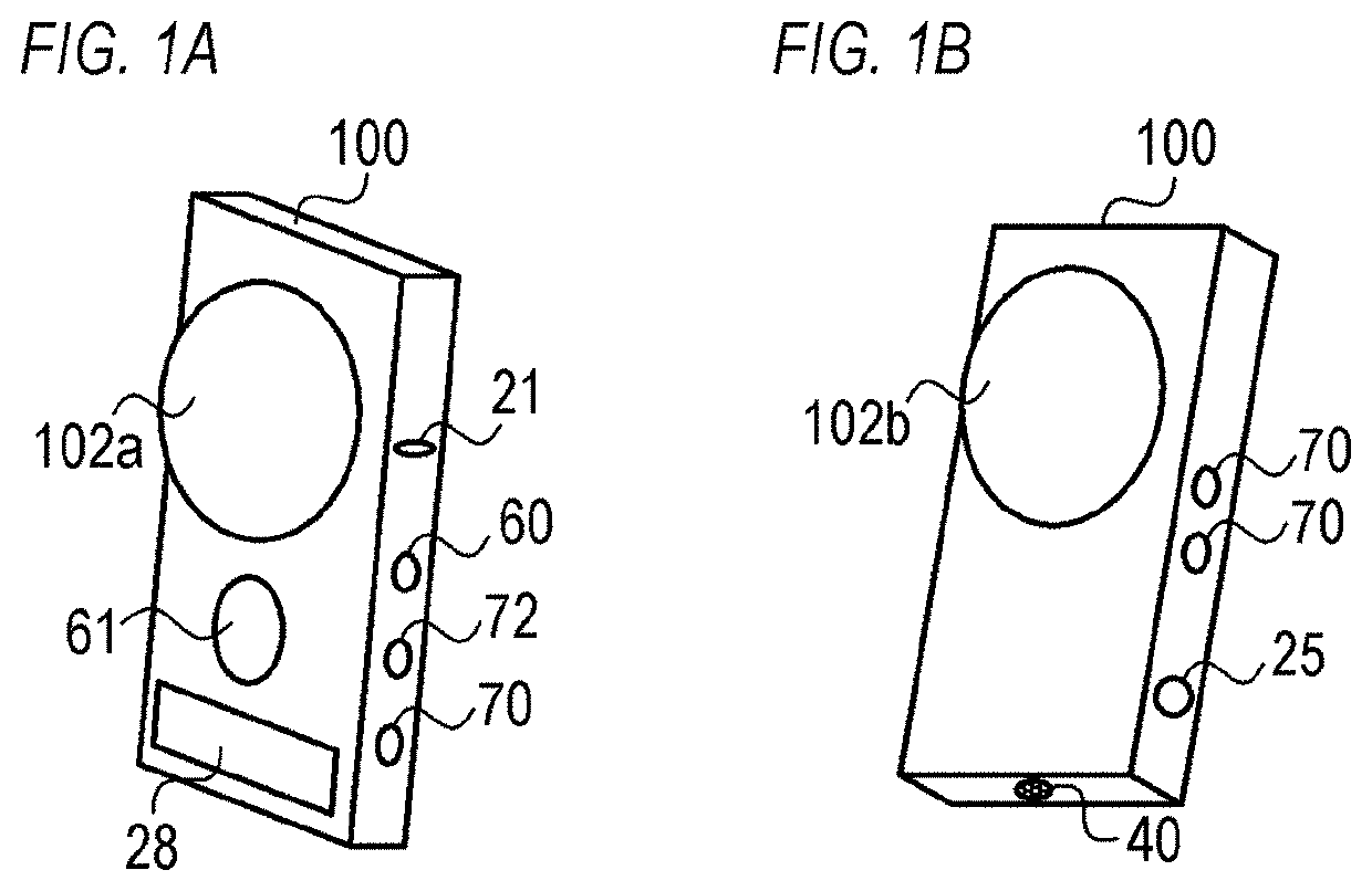
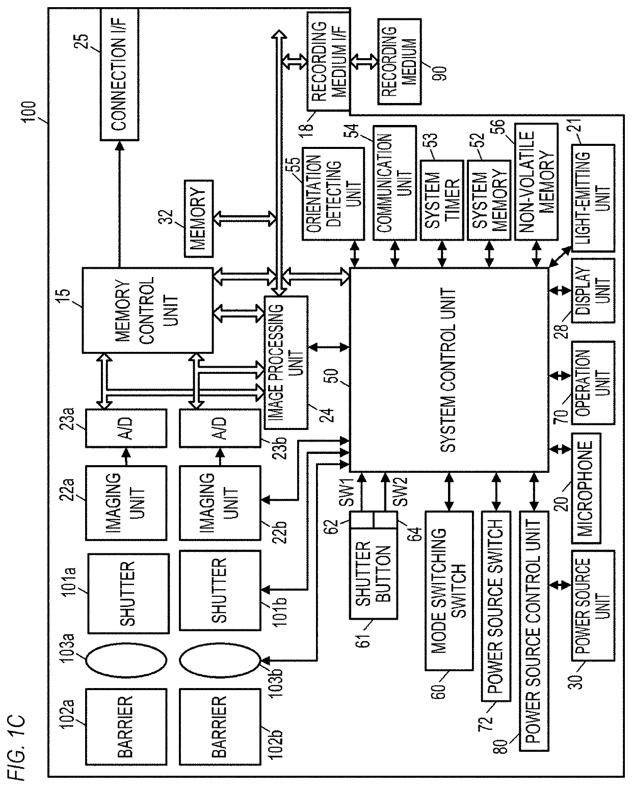
[0026]Hereinbelow, preferred embodiments of the present invention will be described with reference to the drawings. FIG. 1A is a front perspective view (external view) of a digital camera 100 that is an example of an imaging apparatus according to the present embodiment. FIG. 1B is a rear perspective view (external view) of the digital camera 100. The digital camera 100 is a camera (omnidirectional camera; spherical camera) for capturing an omnidirectional image (spherical image).

[0027]A barrier 102a is a protective window for a front camera unit that has a range ahead of the digital camera 100 as a shooting range. The front camera unit is, e.g., a wide-angle camera unit that has, as the shooting range, a wide range of not less than 180 degrees in each of an up-and-down direction and a left-and-right direction ahead of the digital camera 100. A barrier 102b is a protective window for a rear camera unit that has a range behind the digital camera 100 as a shooting range. The rear came...


PUM


Abstract

An image processing apparatus according to the present invention includes at least one memory and at least one processor which function as: an acquisition unit configured to acquire an image captured by an image capturing apparatus, wherein a part of the image corresponding to a viewing direction is to be displayed on a screen; and a generation unit configured to generate a superimposed image by superimposing a graphic image on a specific part of the image corresponding to a specific viewing direction.

Description

CROSS-REFERENCE TO RELATED APPLICATION[0001]This application is a continuation of application Ser. No. 16 / 562,034, filed Sep. 5, 2019, the entire disclosure of which is hereby incorporated by reference.BACKGROUND OF THE INVENTIONField of the Invention[0002]The present invention relates to an image processing apparatus, an image processing method, and a non-transitory computer readable medium.Description of the Related Art[0003]There is known an imaging apparatus capable of easily capturing a fully spherical image in a 360-degree direction (omnidirectional image; all-around image; 360-degree image) by one shooting (capturing) operation. There is also known an imaging apparatus having, as a shooting range, a wide range of not less than 180 degrees, though not reaching 360 degrees. In addition, there is known a method in which part of an image captured by the above imaging apparatus (image of a wide area; wide-area image) is displayed as a display area in a display unit (display appara...

Claims


Application Information

Patent Timeline
Patent Type & Authority Applications(United States)
IPC IPC(8): H04N5/232H04N5/272
CPCH04N5/232939H04N5/272H04N5/23238H04N5/265H04N13/156H04N13/261H04N13/344H04N23/62H04N23/698H04N23/633H04N23/667H04N21/816H04N21/4312H04N21/85406H04N21/4223H04N21/21805G06T3/4038
Inventor OYAMA, YASUFUMI
Owner CANON KK
Why Eureka
Try Eureka