Panel structure for electronic apparatus and electronic apparatus

Inactive Publication Date: 2007-02-08
FUJITSU GENERAL LTD +1
View PDF6 Cites 0 Cited by
  • Summary
  • Abstract
  • Description
  • Claims
  • Application Information

AI Technical Summary

Benefits of technology

[0036] According to the invention, the light emitted from the light source can b

Problems solved by technology

In the conventional structure, however, the appearance of a design image remains s

Method used


Image

  • Panel structure for electronic apparatus and electronic apparatus
  • Panel structure for electronic apparatus and electronic apparatus
  • Panel structure for electronic apparatus and electronic apparatus

Examples


first embodiment

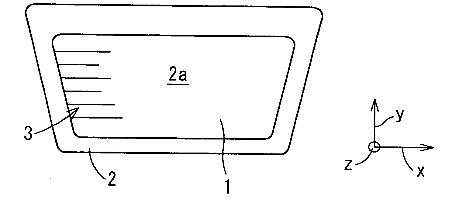
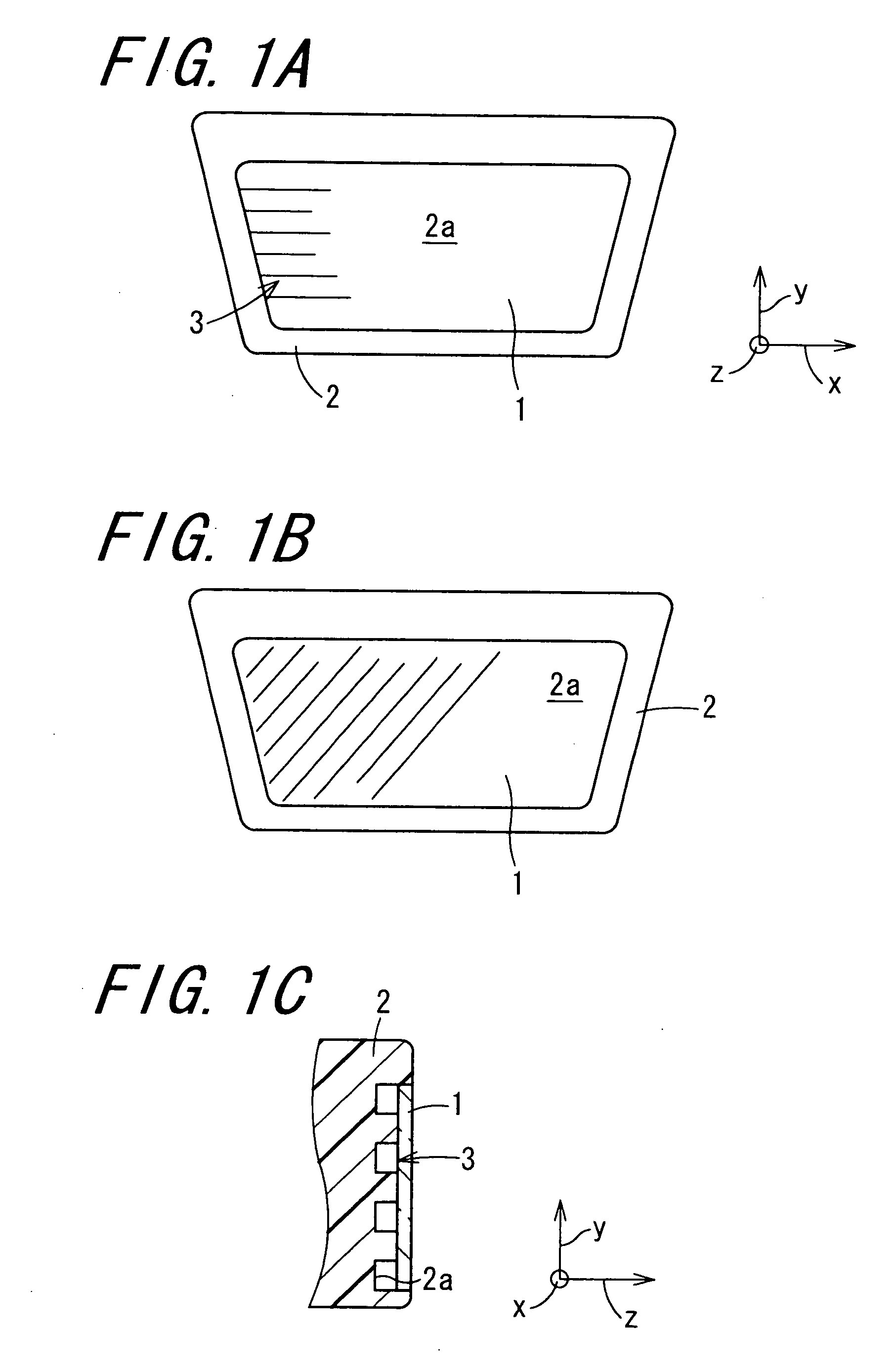
[0049] That part of the panel main body 2 which constitutes the quadrilateral frame portion, namely a recess 2a, is subjected to a processing of applying a design to form an asperity or embossing pattern which is visually perceptible through the panel 1. Such a design-applied portion 3 is formed integrally with the panel main body 2 in the Moreover, the panel main body 2 has, at its x direction-wise opposite ends, a light-guiding plate and a plurality of light emitting diodes (LED for short) acting as a light source (not shown in the figures). A plurality of LEDs disposed at one x direction-wise end of the panel main body 2 are spaced out from one another along the y direction at a constant interval, so as for light emitted to one z direction from each of the LEDs to enter one x direction-wise end of the panel 1 by way of the light-guiding plate. The light incident upon one x direction-wise end of the panel 1 is then conduct to the other x direction-wise end of the panel 1 (refer t...

seventh embodiment

[0061]FIGS. 7A and 7B are views of the panel structure according to the invention, with FIG. 7A showing a front view schematically illustrating a light-shade distribution in a panel, and FIG. 7B showing a front view illustrating dot and pitch adjustment in medium printing. In such a structure as that in which light emitted from a light source is conducted so as to travel simply from one end to the other end in a panel (conventional structure), as shown in FIG. 7A, the opposite x direction-wise ends of the panel are brighter than the other area because of the close proximity to the light source. That is, the value of light density in part of the panel as observed in the z direction is higher relatively to the value of light density in the midportion of the panel as observed in the x direction. In contrast to such a conventional panel structure in which the light density value varies greatly along the x direction, in this construction, as shown in FIG. 7B, by making adjustment to the ...


PUM


Abstract

There is provided a panel structure for an electronic apparatus that is capable of exhibiting two types of design images. During daytime hours for example, a design-applied portion of a panel main body can be visually recognized through a panel made of a light transmitting material. During nighttime hours for example, when light is conducted from one X direction-wise end to the other x direction-wise end in the panel, as well as from the other x direction-wise end to one X direction-wise end in the panel 1, the design-applied portion is shielded with the light illuminating the panel. In this way, by making a difference between the daytime visual impression and the nighttime visual impression of the panel, it is possible to impart two types of design images to the panel structure.

Description

BACKGROUND OF THE INVENTION [0001] 1. Field of the Invention [0002] The present invention relates to a panel structure for an electronic apparatus, and an electronic apparatus having the same, and more particularly to a technology in panel structure applicable to a design panel section of an in-vehicle radio, for example. [0003] In the specification and claims, the term “design-applied portion” refers to a portion which was subjected to a process of applying a design, and the term “printing-processed portion” refers to a portion which was subjected to a process of printing. [0004] 2. Description of the Related Art [0005] There has been known to date a practicable technology in which characters are discernible by allowing light emitted from a light source to pass mainly through the character part of an operating button in the design panel section of an in-vehicle radio, for example (refer to Japanese Unexamined Patent Publication JP-A 2000-106049, for example). [0006] In the conventi...

Claims


Application Information

Patent Timeline
IPC IPC(8): B32B1/00
CPCB60R13/02Y10T428/24736B60R2013/0287
Inventor YAKATA, KOJIUKAI, NOBUYUKIYURI, SHINSUKEHISATUGU, SHINJIYAMASHITA, YOSHITUGUTAKAHASHI, HISAOANDO, KOICHI
Owner FUJITSU GENERAL LTD
Why Eureka
Try Eureka