LED lamp incorporating remote phosphor with heat dissipation features

a technology of remote phosphor and led lamps, which is applied in the direction of discharge tube main electrodes, semiconductor devices of light sources, lighting and heating apparatus, etc., can solve the problems of heat retention, heat loss may occur when the light is reflected, and experience limitations based on the device structure, so as to reduce or eliminate the negative impact, reduce or eliminate the spread of heat, and reduce or eliminate the effect of loss

Active Publication Date: 2011-09-08
IDEAL IND LIGHTING LLC
View PDF102 Cites 62 Cited by
  • Summary
  • Abstract
  • Description
  • Claims
  • Application Information

AI Technical Summary

Benefits of technology

[0013]The present invention provides various embodiments of lamps and bulbs that are efficient, reliable and cost effective. The different embodiments can be arranged with remote conversion material, which helps reduce or eliminate the spread of heat from the light emitters to the phosphor material. The lamps and bulbs can also comprise thermal management features that allow for efficient conduction of conversion generated heat away from the remote conversion material. This reduces or eliminates the negative impact that elevated temperature can have on efficiency and reliability of the conversion material. In different embodiments that conversion material can comprise a phosphor carrier that can be 2-dimensional shaped.

Problems solved by technology

While the reflective cup 13 may direct light in an upward direction, optical losses may occur when the light is reflected (i.e. some light may be absorbed by the reflective cup due to the less than 100% reflectivity of practical reflector surfaces).
In addition, heat retention may be an issue for a package such as the package 10 shown in FIG. 1, since it may be difficult to extract heat through the leads 15A, 15B.
These types of LED chips have been used in different lamps, but experience some limitations based on the structure of the devices.
This elevated operating temperature can cause degradation of the phosphor material, the binding material, and / or the encapsulant material over time.
It can also cause a reduction in phosphor conversion efficiency and consequently often a shift in the perceived color of the LED light.
In applications where the phosphor is located in close proximity to the chip (e.g., conformally coated onto the chip), the high local density of excitation photons emerging from the chip surface can lead to very high local heating and hence high peak temperatures in the phosphor layer.
However, in many remote phosphor arrangements the heat from phosphor conversion heating generally has inadequate heat dissipation paths to dissipate the phosphor conversion heat.
Without an effective heat dissipation pathway, thermally isolated remote phosphors may suffer from elevated operating temperatures that in some instances can be even higher than the temperature in comparable conformal coated layers.

Method used


Image

  • LED lamp incorporating remote phosphor with heat dissipation features
  • LED lamp incorporating remote phosphor with heat dissipation features
  • LED lamp incorporating remote phosphor with heat dissipation features

Examples


Embodiment Construction

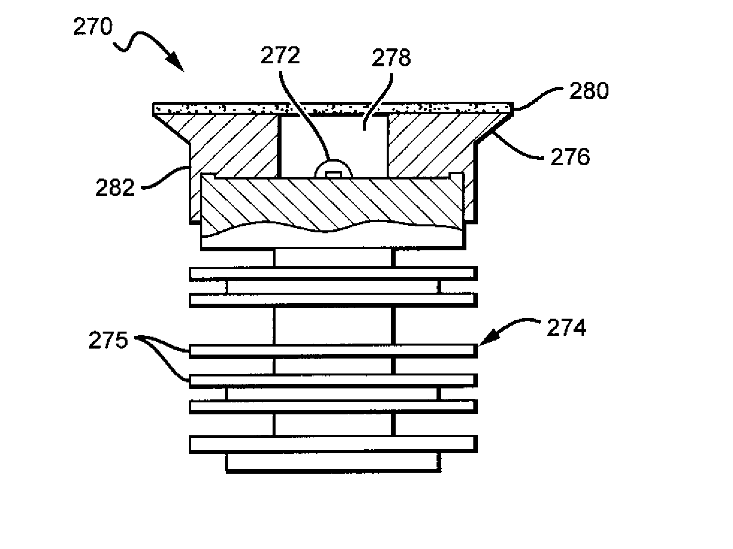
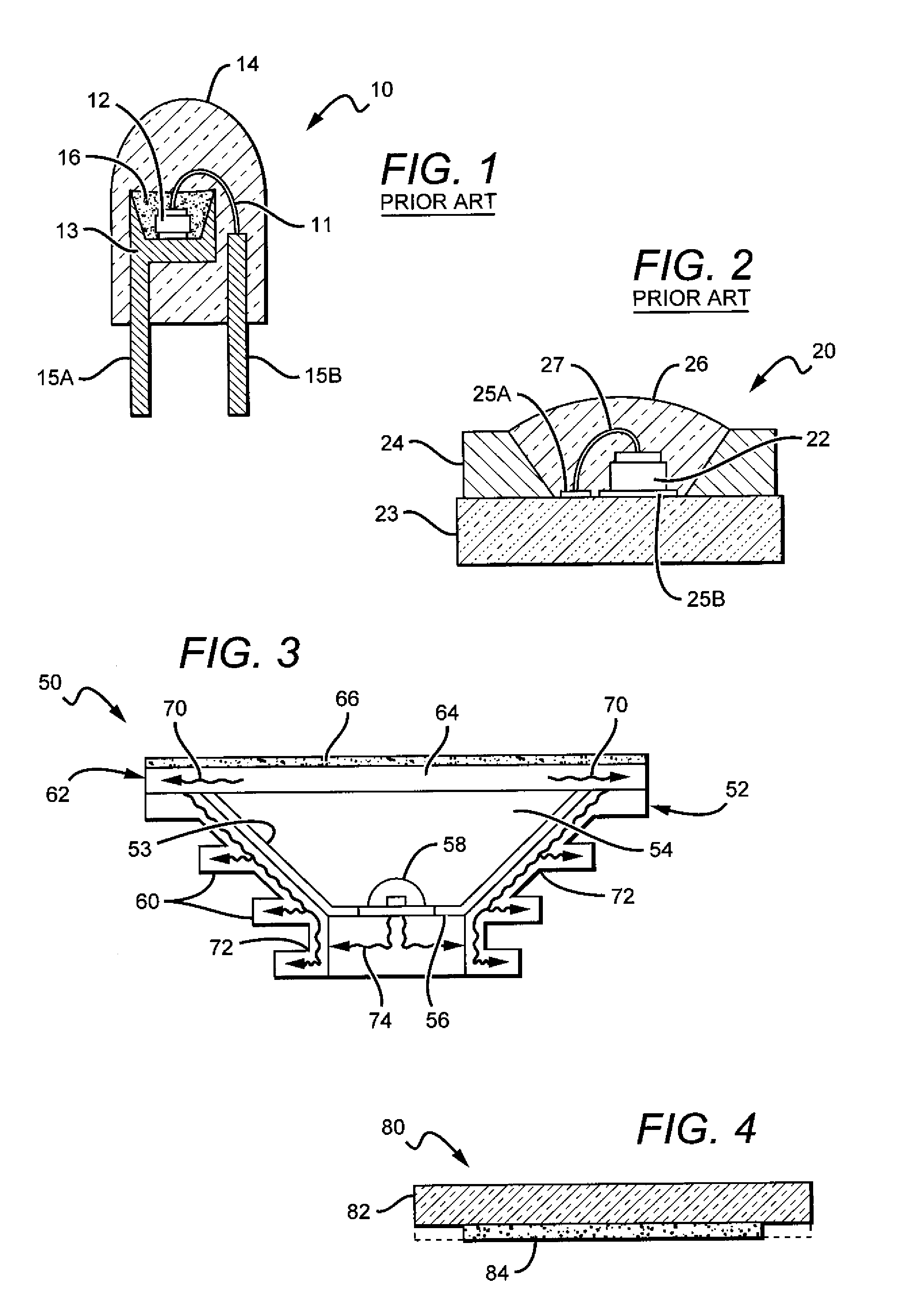
[0034]The present invention is directed to different embodiments of lamp or bulb structures comprising a remote conversion material that can be arranged so that less heat from the emitters heats the conversion material, with the remote conversion material also capable of being operated without the substantial build-up of heat in the conversion material due to the light conversion process. This reduces or eliminates the negative impact that elevated temperature can have on efficiency and reliability of the conversion material. The present invention is also directed to lamps comprising features that mask the conversion material from the view by the lamp user, and can also disperse or redistribute the light from the remote conversion material and / or the lamp's light source into a desired emission pattern.

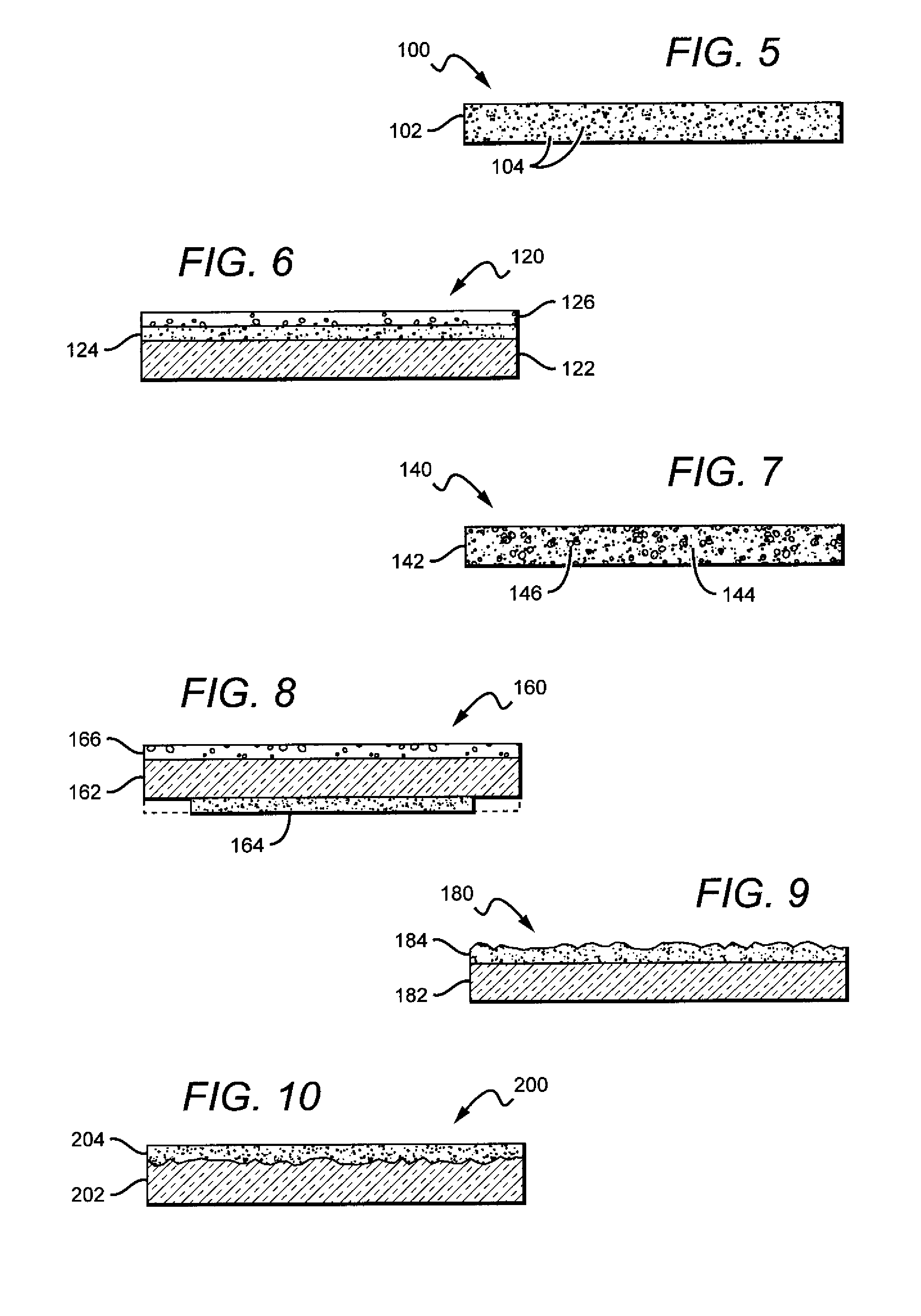
[0035]Different embodiments of the lamps can have many different shapes and sizes and in different lamp embodiments the conversion material can comprise one or multiple conversion mate...


PUM


Abstract

An LED lamp or bulb is disclosed that comprises a light source, a heat sink structure and a remote planar phosphor carrier having at least one conversion material. The phosphor carrier can be remote to the light sources and mounted to the heat sink so that heat from the phosphor carrier spreads into the heat sink. The phosphor carrier can comprise a thermally conductive transparent material and a phosphor layer, with an LED based light source mounted to the heat sink such that light from the light source passes through the phosphor carrier. At least some of the LED light is converted by the phosphor carrier, with some lamp embodiments emitting a white light combination of LED and phosphor light. The phosphor arranged according to the present invention can operate at lower temperature to thereby operate at greater phosphor conversion efficiency and with reduced heat related damage to the phosphor.

Description

[0001]This application claims the benefit of U.S. Provisional Patent Application Ser. No. 61 / 339,516, filed on Mar. 3, 2010, U.S. Provisional Patent Application Ser. No. 61 / 339,515, filed on Mar. 3, 2010, U.S. Provisional Patent Application Ser. No. 61 / 366,437, filed on Sep. 24, 2010, U.S. Provisional Application Ser. No. 61 / 424,665, filed on Dec. 19, 2010, U.S. Provisional Application Ser. No. 61 / 424,670, filed on Dec. 19, 2010, U.S. Provisional Patent Application Ser. No. 61 / 434,355, filed on Jan. 19, 2011, U.S. Provisional Patent Application Ser. No. 61 / 435,326, filed on Jan. 23, 2011, U.S. Provisional Patent Application Ser. No. 61 / 435,759, filed on Jan. 24, 2011. This application is also a continuation-in-part from, and claims the benefit of, U.S. patent application Ser. No. 12 / 848,825, filed on Aug. 2, 2010, U.S. patent application Ser. No. 12 / 889,719, filed on Sep. 24, 2010, and U.S. patent application Ser. No. 12 / 975,820, filed on Dec. 22, 2010.[0002]This invention was made ...

Claims


Application Information

Patent Timeline
Patent Type & Authority Applications(United States)
IPC IPC(8): H01J61/52
CPCF21K9/00F21V29/85F21Y2101/02H01L33/644F21Y2105/001F21K9/56F21V29/006H01L2224/48091H01L2224/48247H01L2224/73265F21V29/004F21V29/767F21V29/75H01L2924/00014F21Y2105/10F21Y2115/10F21V29/502F21V29/506F21V9/30F21K9/64F21V29/76
Inventor TONG, TAOLETOQUIN, RONANKELLER, BERNDTARSA, ERIC
Owner IDEAL IND LIGHTING LLC
Why Eureka
Try Eureka