Safe purging of water from fuel cell stacks

a fuel cell and stack technology, applied in the direction of fuel cells, reactant parameter control, electrical equipment, etc., can solve the problems of causing hazardous gas mixtures, and reducing the efficiency of the fuel cell, so as to achieve a small hydrogen loss

Inactive Publication Date: 2005-06-30
NUVERA FUEL CELLS
View PDF4 Cites 55 Cited by
  • Summary
  • Abstract
  • Description
  • Claims
  • Application Information

AI Technical Summary

Benefits of technology

[0012] In one aspect, the invention comprises an apparatus designed to prevent the release of hydrogen in a flammable concentration from a fuel cell stack. The anode compartment of the fuel cell is purged, periodically or at variable intervals, and the anode gas, preferably after at least partial removal of hydrogen by the action of the stack, is released through a calibrated orifice, or a functionally similar flow restriction. The calibrated orifice leads into a conduit that carries the cathode gas that is leaving the stack, and the anode and cathode gases mix. The orifice is sized so that, at the maximum designed or possible pressure in the anode compartment, and at the normal or lowest normal operating pressure of the cathode compartment, the flow rate of anode gas will be sufficiently low that its concentration, after mixing with the cathode gas, will not exceed the lower flammable limit (LFL) of hydrogen in air. Preferably, a significant margin of safety is provided, so that the final concentration is less than one half of the LFL or, more preferably, less than one quarter of the LFL.
[0013] In another aspect of the invention, a method is provided for operating a fuel cell stack so as to allow purging of water from the stack while keeping the hydrogen concentration in the efflux from the cell below the LFL. In another aspect of the invention, particular patterns of opening and closing of valves are used to conduct purges efficiently and with little hydrogen loss.

Problems solved by technology

However, the low temperature PEM cell has the disadvantage of typically operating below the boiling point of water which allows product water to accumulate in the fuel cell, where it can block access of gas to the active membrane, as is well known (c.f.
The problem is particularly acute when fuel cells are assembled in series into a fuel cell stack (a “stack”), since the stack has manifolding to deliver air and hydrogen to the individual cells which manifolding provides an additional place where water can accumulate.
The problem of water management is further exacerbated by the necessity to keep the membrane wet, since water absorbed on charged groups in the membrane is the route through which protons pass through the membrane.
Moreover, the passage of protons through the membrane tends to drag water molecules through the membrane.
Purging the anode side, however, tends to entail release of hydrogen and releasing hydrogen not only reduces the efficiency of the fuel cell, but can also create a hazardous gas mixture.
However, no means is provided for effecting a vigorous purge to force water out of the fuel cell membrane area in the stack.
But in a standalone stack operating on hydrogen, the release of hydrogen affects not only efficiency, but also safety.
None of the above proposals addresses the problem of safety.
When fuel cells are to be used in buildings, or in automobiles, the generation of a flammable mixture is generally not considered to be acceptable.
This is a problem that has to be solved when using purified hydrogen in fuel cells.

Method used


Image

  • Safe purging of water from fuel cell stacks
  • Safe purging of water from fuel cell stacks
  • Safe purging of water from fuel cell stacks

Examples


Embodiment Construction

[0017] The invention comprises a preferred regulatory means for controlling hydrogen concentration, apparatuses for implementing a controlled hydrogen purge in the context of purges to remove water from a stack, and methods of operating the apparatus.

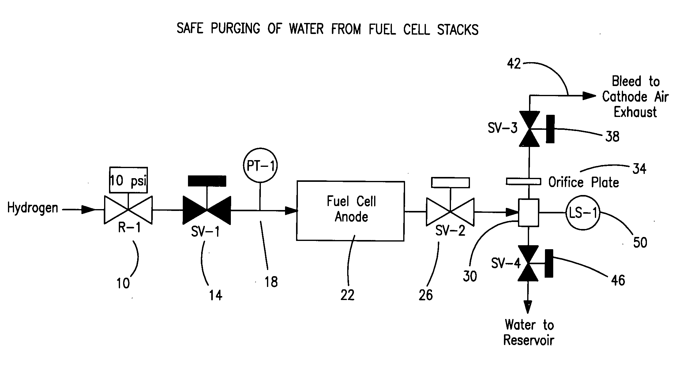
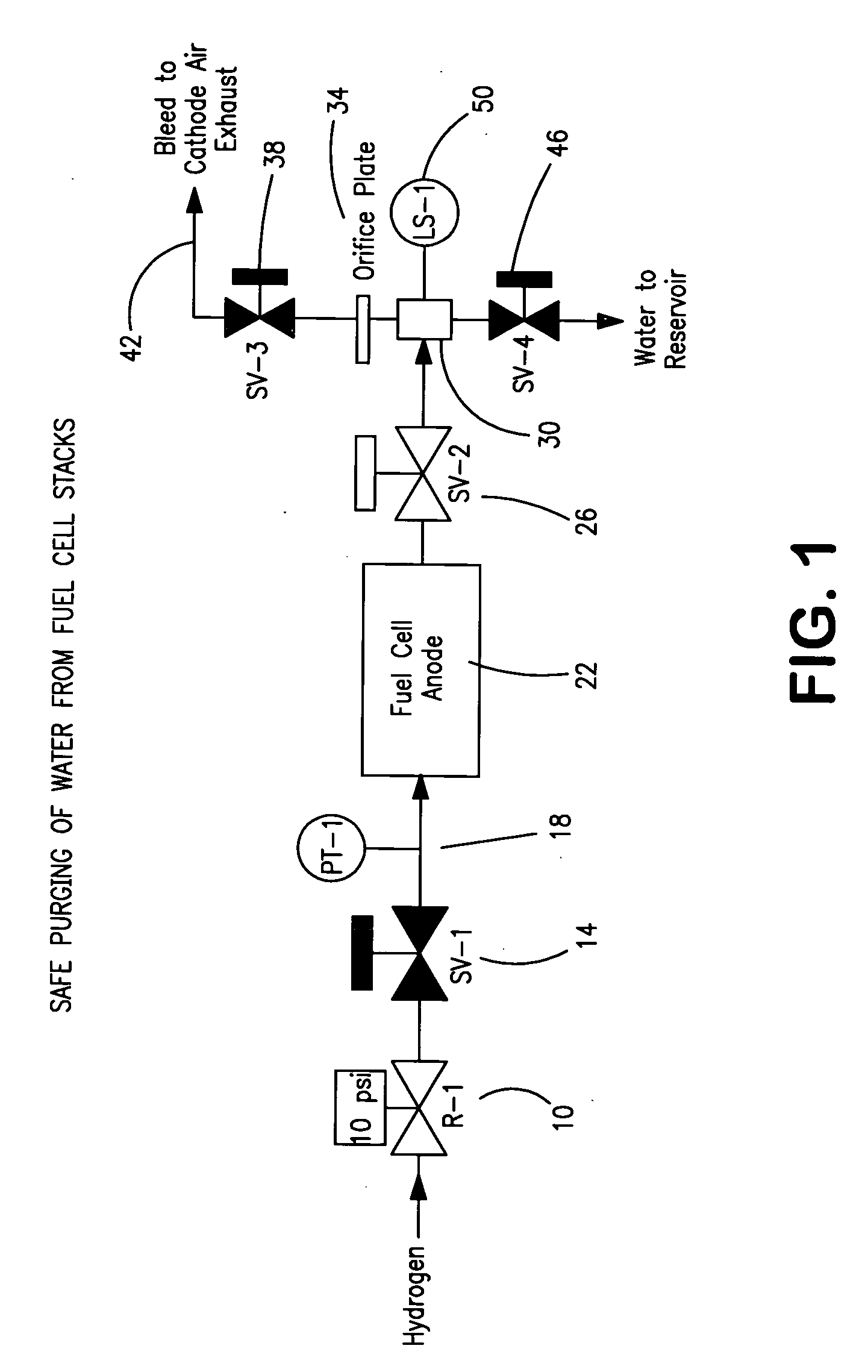
[0018] A schematic diagram of a preferred embodiment of the regulatory system is shown in FIG. 1 which shows an anode (fuel) compartment of a fuel cell stack, and the system regulating the supply of hydrogen to and the venting of hydrogen from a fuel cell stack. Hydrogen is fed via a pressure regulator 10 to a normally-closed solenoid valve 14, and then into fuel cell anode compartment 22. A pressure sensor 18 can be located on the inlet to the fuel cell (as shown) or at the outlet. Anode exhaust, containing hydrogen as well as non-combustible gases from the fuel and from the air by diffusion across the membrane, leaves the anode compartment via a normally-open solenoid valve 26, and passes into recycle tank 30. Anode exhaust flows int...


PUM

PropertyMeasurementUnit
temperaturesaaaaaaaaaa
lengthaaaaaaaaaa
concentrationaaaaaaaaaa

Abstract

Methods and devices are provided for purging fuel cells of water and accumulated non-reactive gases whereby the systems are constructed to dilute any emitted hydrogen below its inflammability limit for increased safety.

Description

PRIOR APPLICATION [0001] This application claims the benefit of U.S. Provisional Patent Application Ser. No. 60 / 534,348 filed Dec. 31, 2003.BACKGROUND OF THE INVENTION [0002] There is increasing interest in fuel cells for various uses and, in particular, the “PEM” type of fuel cell is of great interest, especially for smaller or mobile operations. In a PEM fuel cell, hydrogen is catalytically decomposed on one side of a membrane, the protons pass through the membrane, and the electrons, after doing work as an electric current, unite with the protons and with oxygen to produce water and heat. [0003] One attractive feature of PEM cells is that they operate at relatively low temperatures, in the range of about 60 to 100° C. This improves speed of startup, and improves safety. However, the low temperature PEM cell has the disadvantage of typically operating below the boiling point of water which allows product water to accumulate in the fuel cell, where it can block access of gas to the...

Claims


Application Information

Patent Timeline
Patent Type & Authority Applications(United States)
IPC IPC(8): H01M8/04
CPCH01M8/04097H01M8/04179H01M8/04201H01M8/04231H01M8/04388Y02E60/50H01M8/04753H01M8/04761H01M8/04798H01M8/04828H01M8/04589
Inventor TURCO, FRANCESCOFULLER, WARE D.
Owner NUVERA FUEL CELLS
Why Eureka
Try Eureka