Method and system for reducing line separation artifacts in interlaced image projection

a line separation artifact and interlaced image technology, applied in the field of line separation artifact reduction in interlaced image projection, can solve the problems of undesirable observational artifacts that are difficult to eliminate, interlaced scan configurations, etc., and achieve the effects of reducing flicker observed, increasing perceived frame rate, and difficult to elimina

Pending Publication Date: 2021-09-30
MAGIC LEAP INC
View PDF4 Cites 0 Cited by
  • Summary
  • Abstract
  • Description
  • Claims
  • Application Information

AI Technical Summary

Benefits of technology

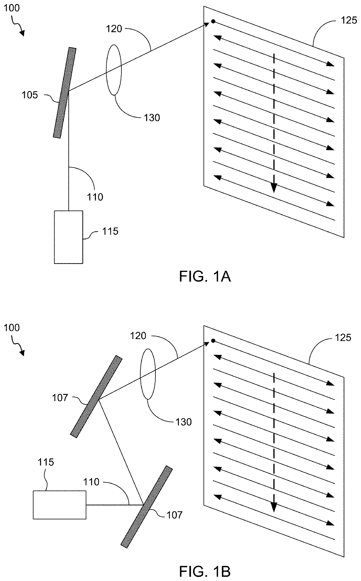
[0003]Scanning image displays and projection systems may employ a progressive scan or an interlaced scan configuration. Interlaced scan configurations may be desirable to accommodate particular geometries or component operational parameters, to increase a perceived frame rate, and / or to reduce flicker observed by a user. However, interlaced scan configurations may introduce other observational artifacts that may be undesirable and difficult to eliminate, such as line separation artifacts that may be observed by a user while the user is scanning across an image projected by a scanning image display or projection system. Embodiments described herein provide scanning image display systems and projection systems that feature interlaced scan configurations that exhibit reduced observational artifacts that can degrade viewability of images projected using a scanning image display system. In some embodiments, scanning image display systems can employ a multiple interlaced scan configuration and / or a variable scan pattern from image to image.
[0017]Various techniques may be employed by the image projection systems described herein to improve overall image quality and / or to reduce display or perception artifacts. By using pseudo- or quasi-random selection or identification of scan patterns, scan patterns can be reused at later times for display of subsequent images without encountering display or perception artifacts. For example, in some embodiments, identifying the plurality of scan patterns includes identifying, from among the set of multiple different scan patterns, the plurality of scan patterns previously used by the control circuitry to display images of virtual content. Optionally, the plurality of scan patterns may be identified in a pseudo- or quasi-random manner for the plurality of images of virtual content in the sequence, respectively. Optionally, identifying, from among the set of multiple different scan patterns, the plurality of scan patterns for the plurality of images of virtual content in the sequence includes selecting, from among the set of multiple different scan patterns, a plurality of scan patterns for the plurality of images of virtual content in the sequence, respectively, in a pseudo- or quasi-random manner. Further, by using pseudo- or quasi-random selection or identification of scan patterns, repeated scan patterns may be spaced in time from one another by a sufficient duration to limit display or perception artifacts, such as line separation artifacts.
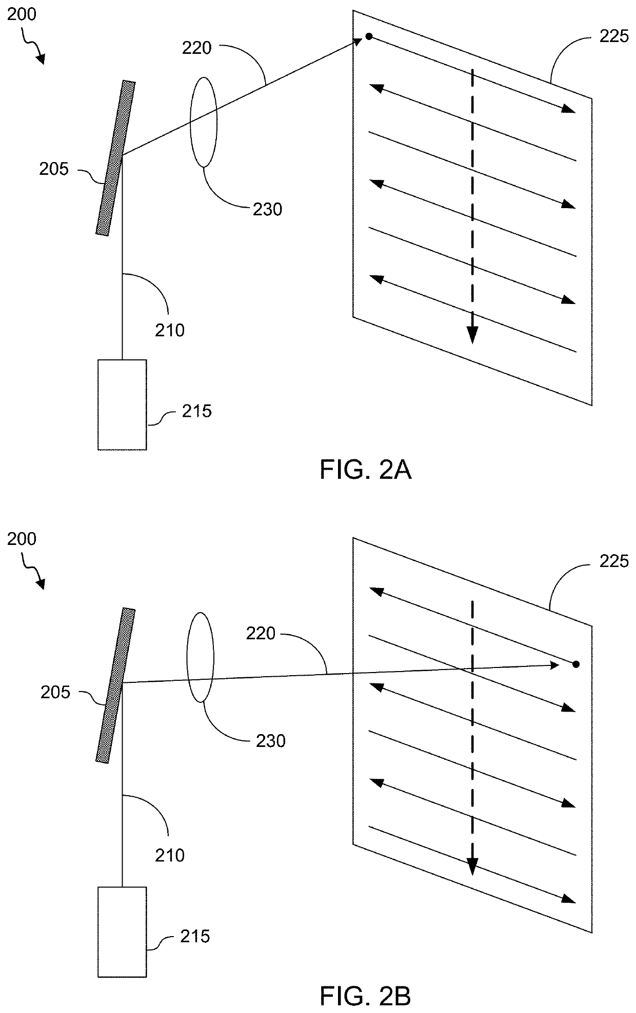
[0018]As described in more detail herein, a large number of different scan patterns may be available for use for displaying different images in the sequence. Use of a large number of different scan patterns may be advantageous for limiting or reducing image artifacts. Each image, however, may be displayed using a subset of different scan patterns from this larger number. For example, the set of multiple different scan patterns optionally comprises a set of k different scan patterns, k representing a value greater than two. The plurality of images in the sequence may be displayed using a quantity of m different scan patterns, m representing a value greater than one and less than or equal to k. The control circuitry may be configured to control the actuator of the scanning mirror to induce a sequence of m different oscillations in the scanning mirror about the first rotational axis in accordance with each of the plurality of scan patterns identified for the plurality of images of virtual content in the sequence, respectively. As an example, the oscillations may have a sinusoidal or substantially sinusoidal shape. Depending on the configuration, k may be an integer multiple of m. Optionally, the m different oscillations are offset in phase from each other by a minimum of about 2π / k radians. By offsetting the various oscillations, it is possible to limit repeating the same scan patterns when displaying different images, such as images immediately following one another in the sequence.
[0023]In another aspect, image projection methods are described. Images may be projected, for example, using an image projection system described herein. According to some embodiments, a method for projecting an image comprises generating a modulated light beam, such as a modulated light beam that is modulated according to a plurality of image fields in sequence; illuminating a scanning mirror with the modulated light beam to generate a reflected light beam; and projecting the reflected light beam to generate a plurality of images. Each image of the plurality of images may be generated by projecting multiple image fields in sequence. Projecting the plurality of image fields may include adjusting an orientation of the scanning mirror according to a sequence of scan patterns, such as a sequence of scan patterns corresponding to a randomly selected scan pattern of a plurality of different scan patterns or to a pseudo-randomly or quasi-randomly selected scan pattern of the plurality of different scan patterns. By using a randomly, pseudo-randomly, or quasi-randomly selected scan pattern, image observation artifacts can be reduced by using a number of different scan patterns such that the scan patterns are not repeated exactly from image to image. By using different scan patterns for each image in a series of images, a likelihood that a particular image field will exactly overlap with another image field of a previous or next image when a user's eye is moving will be reduced, as compared to a system in which the same exact scan patterns are used for every image.

Problems solved by technology

However, interlaced scan configurations may introduce other observational artifacts that may be undesirable and difficult to eliminate, such as line separation artifacts that may be observed by a user while the user is scanning across an image projected by a scanning image display or projection system.

Method used


Image

  • Method and system for reducing line separation artifacts in interlaced image projection
  • Method and system for reducing line separation artifacts in interlaced image projection
  • Method and system for reducing line separation artifacts in interlaced image projection

Examples


example 2

[0086 is the image projection system of example 1, wherein the optical subsystem includes one or more laser sources.

[0087]Example 3 is the image projection system of examples 1-2, wherein the scanning mirror comprises a microelectromechanical system (MEMS) mirror having two independently rotatable axes.

[0088]Example 4 is the image projection system of examples 1-3, wherein the scanning mirror comprises two microelectromechanical system (MEMS) mirrors in sequence, wherein each MEMS mirror has one rotatable axis.

[0089]Example 5 is the image projection system of examples 1-4, wherein the scanning mirror has a fast oscillation axis and a slow oscillation axis.

[0090]Example 6 is the image projection system of examples 1-5, wherein the projection optics include one or more lenses, mirrors, beam splitters, filters, prisms, polarizers, waveguides, diffractive optical elements, windows, or any combination of these.

[0091]Example 7 is the image projection system of examples 1-6, wherein each i...

example 12

[0096 is the image projection system of example 11, wherein the first image field, the second image field, the third image field and the fourth image field are generated from a rendered frame corresponding to a first image of the plurality of images.

[0097]Example 13 is the image projection system of examples 1-12, wherein the pseudo-randomly or quasi-randomly selected scan pattern sequence corresponds to a sequence of the plurality of different scan patterns that repeats after multiple images of the plurality of images are projected.

[0098]Example 14 is a method for projecting an image, the method comprising: generating a modulated light beam, wherein the modulated light beam is modulated according to a plurality of image fields in sequence; illuminating a scanning mirror with the modulated light beam to generate a reflected light beam; and projecting the reflected light beam to generate a plurality of images, wherein each image of the plurality of images is generated by projecting m...

example 27

[0111 is a computer program product comprising a non-transitory computer readable storage medium including instructions that, when executed by one or more processors, cause the one or more processors to perform operations including: controlling an optical subsystem so that the optical subsystem emits a modulated light beam modulated according to a plurality of image fields in sequence; and adjusting an orientation of a scanning mirror positioned to intercept the modulated light beam and generate a reflected light beam, wherein adjusting the orientation of the scanning mirror includes actuating an actuator of the scanning mirror according to sequence of scan patterns, wherein the sequence of scan patterns corresponds to a randomly selected scan pattern sequence of a plurality of different scan patterns, to a pseudo-randomly selected scan pattern sequence of the plurality of different scan patterns, or to a quasi-randomly selected scan pattern sequence of the plurality of different sc...


PUM


Abstract

An image display system includes an optical subsystem configured to emit a modulated light beam, and a scanning mirror for generating a reflected light beam that is scanned according to randomly selected or pseudo-randomly selected scan patterns to generate multiple image fields of a multiple interlaced scan image. A plurality of different scan patterns can be cycled through, randomly or pseudo-randomly selected, for the different image fields to reduce artifacts that may be observed while viewing a projected image.

Description

CROSS-REFERENCES TO RELATED APPLICATIONS[0001]This application is a continuation of International Patent Application No. PCT / US2019 / 057039, filed Oct. 18, 2019, entitled “METHOD AND SYSTEM FOR REDUCING LINE SEPARATION ARTIFACTS IN INTERLACED IMAGE PROJECTION,” which claims the benefit of and priority to U.S. Provisional Patent Application No. 62 / 747,916, filed Oct. 19, 2018, entitled “METHOD AND SYSTEM FOR REDUCING LINE SEPARATION ARTIFACTS IN INTERLACED IMAGE PROJECTION,” the entire disclosures of which are hereby incorporated by reference, for all purposes, as if fully set forth herein.BACKGROUND OF THE INVENTION[0002]Scanning display technology has existed since the development of cathode ray tube (CRT) displays. While most modern liquid crystal displays (LCD) use progressive scan for displaying images and video, CRT displays have historically used both progressive scan as well as interlaced scan. In a progressive scan display, the lines of each frame are drawn in sequence, typic...

Claims


Application Information

Patent Timeline
Patent Type & Authority Applications(United States)
IPC IPC(8): G02B26/10G02B26/08G03B21/00H04N9/31
CPCG02B26/101G02B26/0833H04N9/3129H04N9/3161G03B21/008
Inventor EDWIN, LIONEL ERNESTVLASKAMP, BJORN NICOLAAS SERVATIUSMILLER, SAMUEL A.CLARKE, AARON M.
Owner MAGIC LEAP INC
Why Eureka
Try Eureka