Intubation system, method, and device

a technology of intubation system and intubation tube, which is applied in the field of intubation system, can solve the problems of cardiac arrest, cardiac arrest, and difficult second step performance, and achieve the effects of requiring skill and experience, and achieving the effect of reducing the risk of cardiac arres

Pending Publication Date: 2022-06-02
KIM CHONG S
View PDF4 Cites 0 Cited by
  • Summary
  • Abstract
  • Description
  • Claims
  • Application Information

AI Technical Summary

Benefits of technology

[0020]The disclosed subject matter provides a system, method, and device utilized to position an ETT (endotracheal tube) into a laryngeal opening of a patient. The device comprises an overtube having a semirigid proximal portion, a flexible distal tip, and a hood. The semirigid portion includes a proximal end and a distal end. The flexible tip affixes to the distal end of the semirigid portion. The distal end may house a feeder mechanism for displacing the ETT. A hood slideably attached to the distal ...

Problems solved by technology

While the majority of cases of intubations are straightforward and simple, difficulty in airways do occur and can result in catastrophic outcomes such as death, brain damage, cardiopulmonary arrest, tracheotomy, and trauma to the pharynx, larynx, and trachea.
The performance of the second step can be demanding and requires skill and experience.
Whilst laryngoscopes are adequate in certain cases, not infrequently, however, they fail simply because they can expose the airway only to the level of the epiglottis and not beyond.
Should narrowing, swelling, or excessive soft tissue exist below the level of the epiglottis, the usefulness of rigid laryngoscopes is severely limited.
Likewise, its utility is restricted in the presence of factors such as, large tongue, a large tumor in the oral cavity and oropharynx, edematous tongue, receded chin, immobile jaw, elongated upper incisors, stiff and immobile necks, and facial and neck trauma.
Notwithstanding these obvious advantages, challenges still remain because the blade of video laryngoscopes is ordinarily positioned at the vallecula (the point between the base of the tongue and the epiglottis).
In situations where blockage is present beyond the laryngeal blade, i.e. between the to...

Method used


Image

  • Intubation system, method, and device
  • Intubation system, method, and device
  • Intubation system, method, and device

Examples


Embodiment Construction

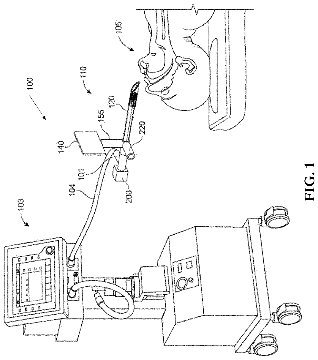
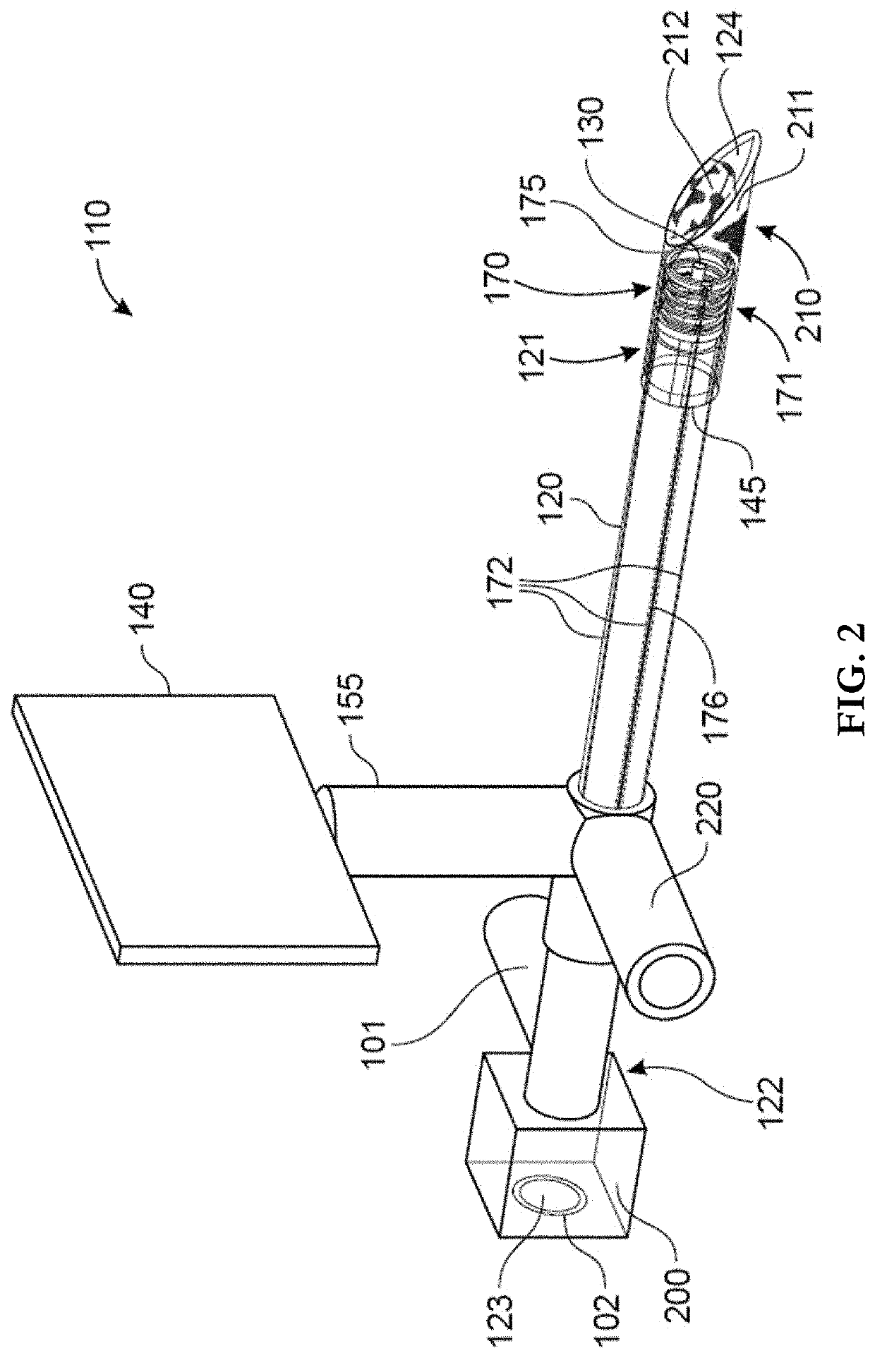
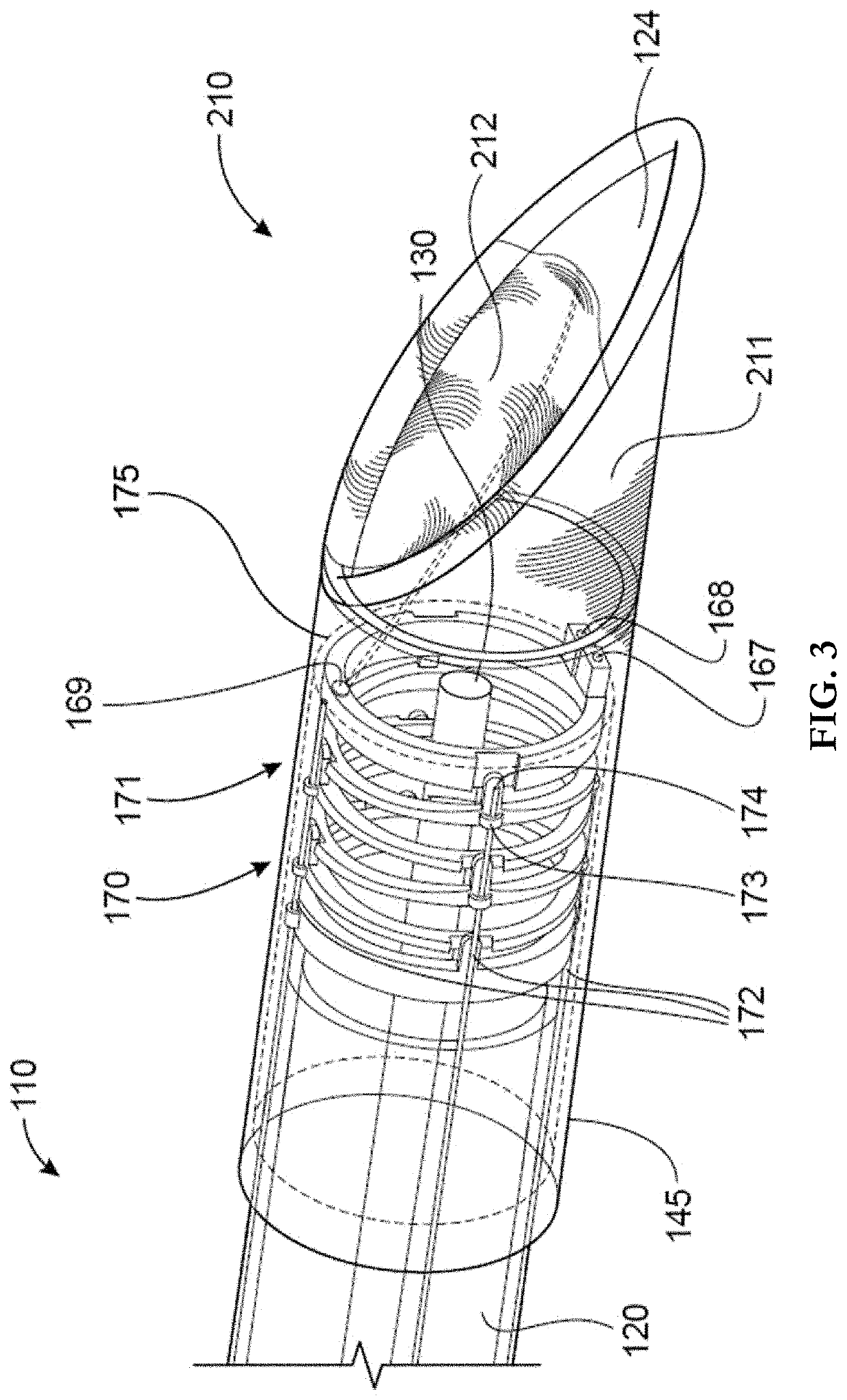
[0044]Reference now should be made to the drawings, in which the same reference numbers are used throughout the different figures to designate the same components.

[0045]It will be understood that, although the terms first, second, third, etc. may be used herein to describe various elements, these elements should not be limited by these terms. These terms are only used to distinguish one element from another element. Thus, a first element discussed below could be termed a second element without departing from the teachings of the present disclosure.

[0046]The terminology used herein is for the purpose of describing particular embodiments only and is not intended to be limiting. As used herein, the singular forms “a”, “an”, and “the” are intended to include the plural forms as well, unless the context clearly indicates otherwise. It will be further understood that the terms “comprises” and / or “comprising” or “includes” and / or “including” when used in this specification, specify the pre...


PUM


Abstract

An intubation device utilizes a steerable endotracheal tube guide, a novel mechanism to automatically position an endotracheal tube at the laryngeal opening, and a novel system for soft tissue retraction to improve visualization of the laryngeal opening. An ETT is positioned within an overtube having proximal and distal ends and a flexible tip. The distal end houses a feeder mechanism for displacing the endotracheal tube through the overtube. A hood includes a stem, base, and expandable body, and may be affixed to the overtube's distal end. The ETT-containing overtube is precisely positioned at a laryngeal opening via positioning effects of body expansion, activation of a tip director, and/or flexible tip articulation. Unhindered visualization of the laryngeal opening is achieved by the expandable body, pushing the soft tissue outwardly and extensibly. An actuation module controls the feeder mechanism as well as the flexible tip to position flexible tip and endotracheal tube.

Description

CROSS-REFERENCE TO RELATED APPLICATIONS[0001]N / AFIELD OF THE INVENTION[0002]This invention relates generally to intubation systems, and more specifically to intubation tube insertion devices that provide a clear, unobstructed pathway to a patient's laryngeal opening.BACKGROUND OF THE INVENTION[0003]The most effective and basic way of securing definitive airway management remains direct laryngoscopy with subsequent placement of an intubation tube.[0004]The laryngoscope consists of a handle and a blade. The blade of a laryngoscope is typically comprised of a flat element usually made of stainless steel and is designed to be placed either in the vallecula (behind the tongue) or posterior to the epiglottis. By lifting up the laryngoscope, then, the mandible, tongue, epiglottis, hyoid bone, and other soft tissue are displaced out of the line of sight of the laryngoscopist in order to expose the glottic opening.[0005]The success of intubation depends on being able to clearly expose the la...

Claims


Application Information

Patent Timeline
IPC IPC(8): A61M16/04A61M16/00
CPCA61M16/0488A61M2205/583A61M16/0418A61M16/0003A61M2205/502A61M2209/084A61M2205/587A61M16/0463A61M2205/0216A61M2205/10A61M16/0409A61M2205/07A61M16/0445A61M16/022A61B1/00082A61B1/2673A61B1/00052A61B1/0055
Inventor KIM, CHONG S.
Owner KIM CHONG S
Why Eureka
Try Eureka