

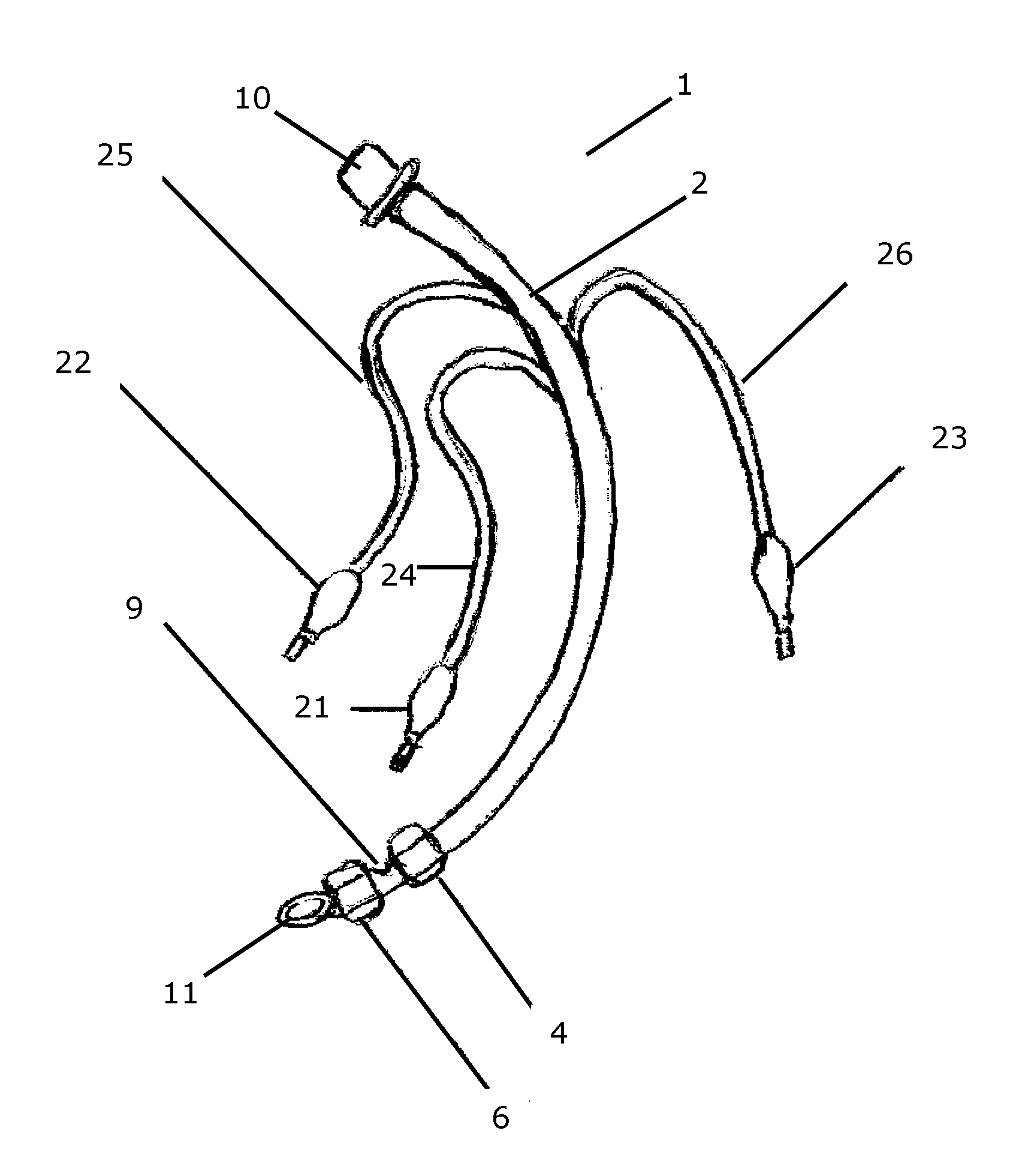
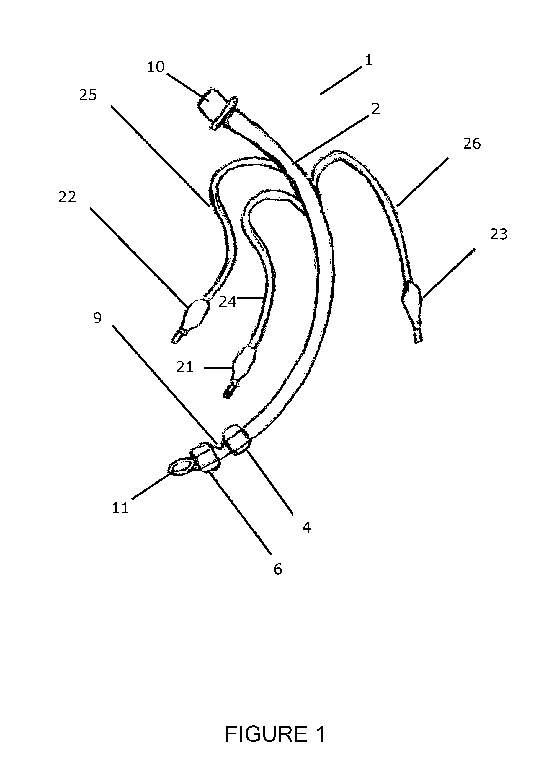
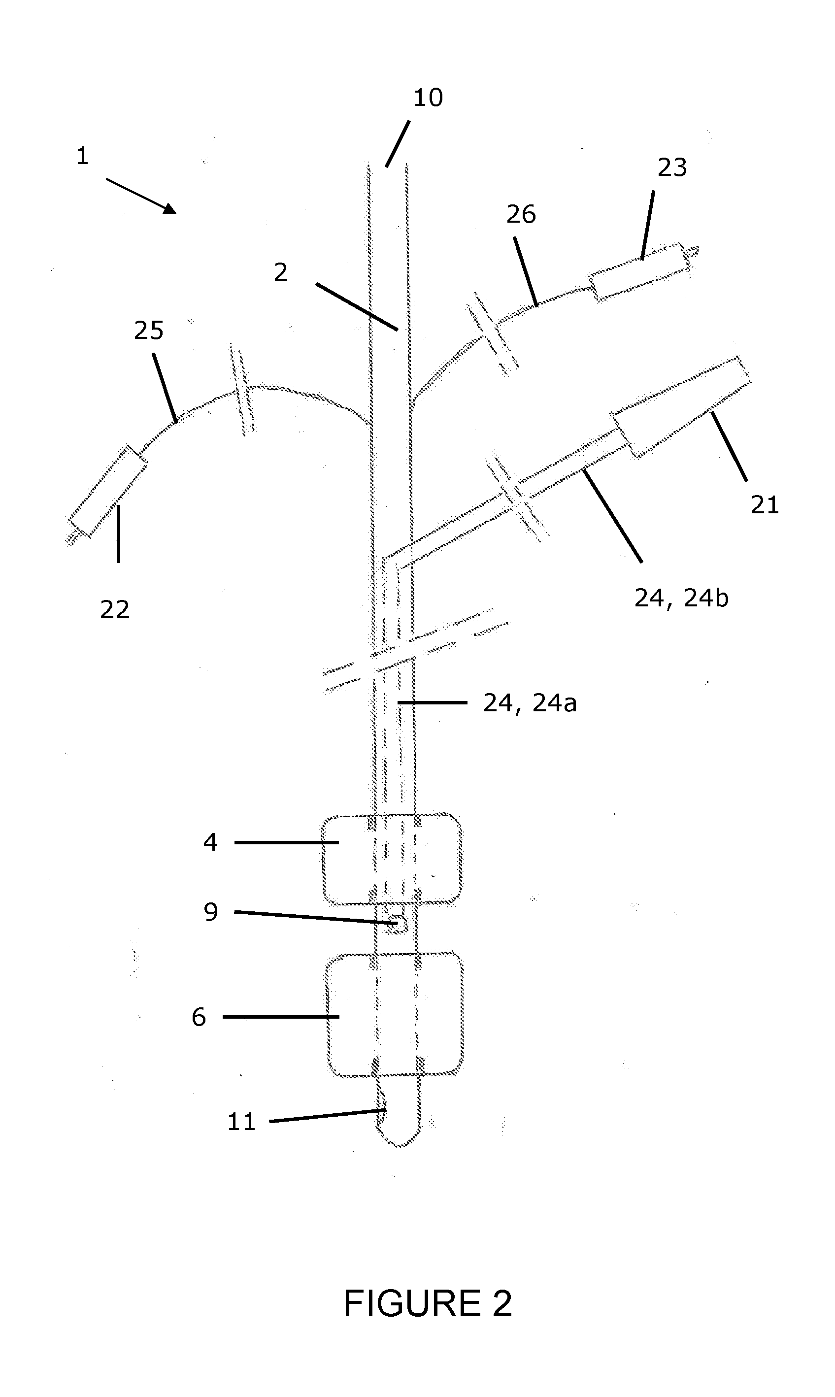
Endotracheal tube for mechanical ventilation
a technology for mechanical ventilation and endotracheal tubes, which is applied in the field of improved endotracheal tubes or patient ventilation tubes, can solve the problems of increased duration of ventilation and icu stay, increased risk of multidrug resistant bacteria, and high attributable mortality
- Summary
- Abstract
- Description
- Claims
- Application Information
AI Technical Summary
Benefits of technology
Problems solved by technology
Method used
Image

Examples
examples
[0120]a) Comparative test
[0121]The present example describes experiments wherein the ability to prevent proximal fluid leakage of a ventilation tube according to the present invention is compared to 3 commercialized single-cuffed ventilation tubes.
[0122]An artificial trachea with jagged inside walls and an internal diameter of 23 mm was used to mimick the in vivo situation. The jagged walls of the artificial trachea closely resemble the real trachea surface and therefore provide more realistic experimental conditions than the glass tubes with smooth inside walls often used in testing such devices. A ventilation tube according to the present invention was compared to 3 commercialized single-cuffed ventilation tubes n° 8: the polyvinyl cuff (classical) Portex®, the polyvinyl cuff (pear-formed) TaperGuard Evac® Mallinckrodt and the polyurethane Microcuff® Kimberly-Clark. The ventilation tubes were positioned in the artificial trachea and 3.4 ml of a methylene blue solution was administ...
PUM
 Abstract
Description
Claims
Application Information