Eureka AIR delivers breakthrough ideas for toughest innovation challenges, trusted by R&D personnel around the world.

Light emitting display panel and light emitting display apparatus using the same

Pending Publication Date: 2022-06-30
LG DISPLAY CO LTD
View PDF4 Cites 0 Cited by
  • Summary
  • Abstract
  • Description
  • Claims
  • Application Information

AI Technical Summary

Benefits of technology

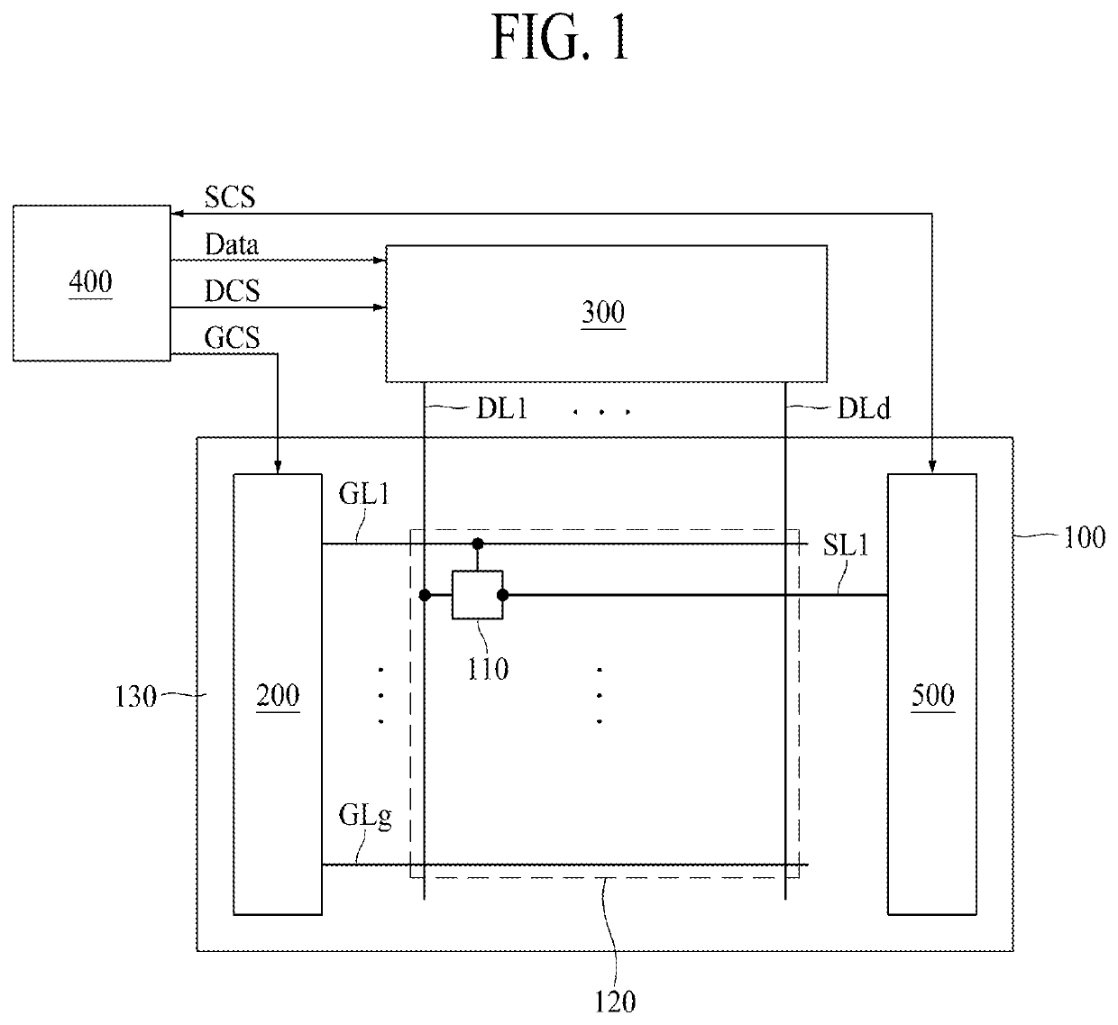
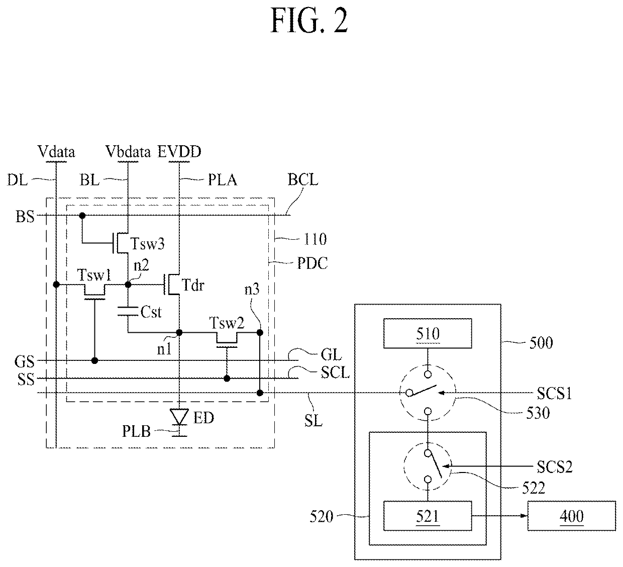
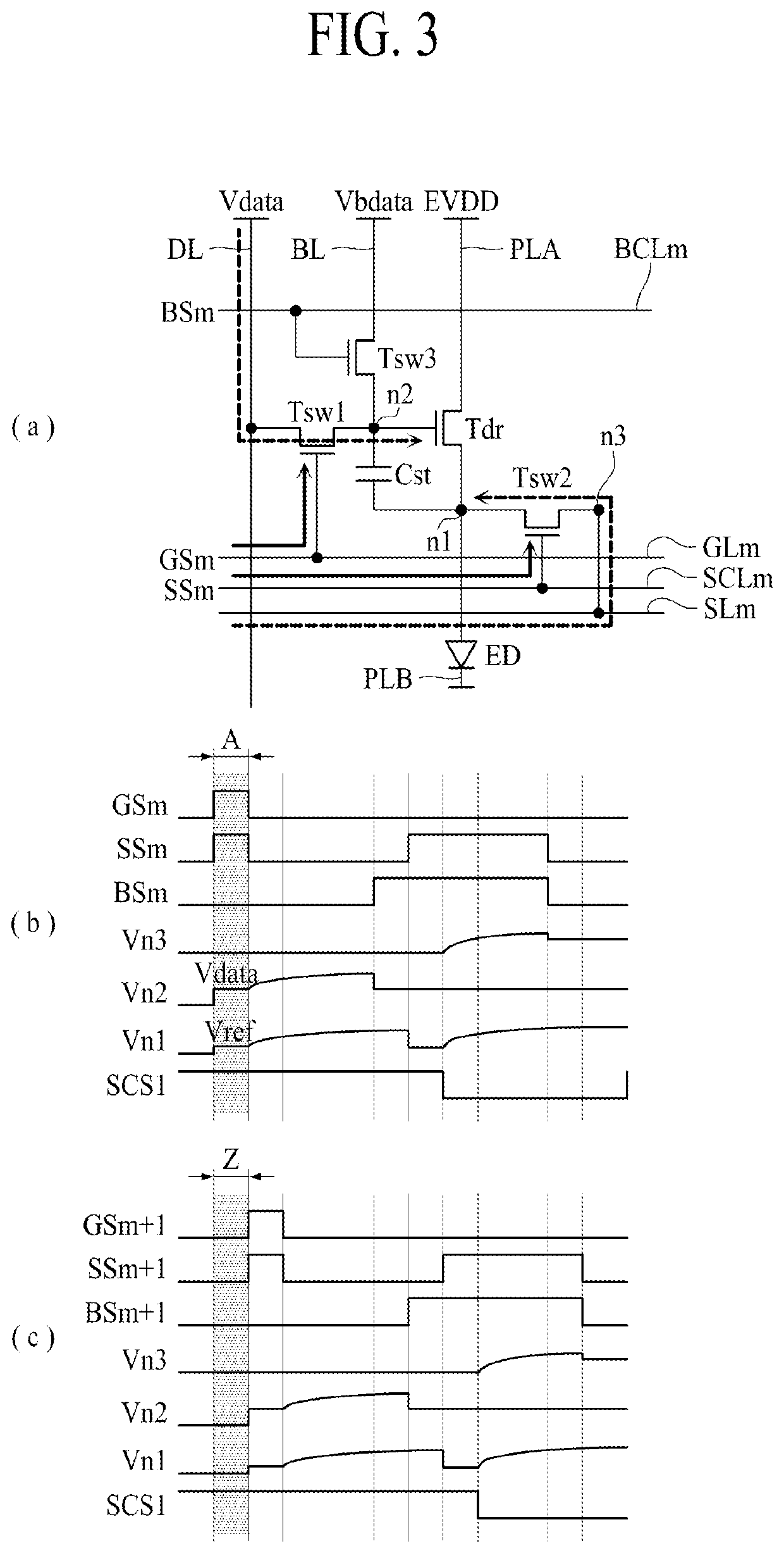
The present invention is directed to a light emitting display panel and a light emitting display apparatus which can prevent the deterioration of the image quality. The technical effects of the invention include the provision of a sensing line in parallel with a gate line, the sensing control line, and a black control line to sequentially connect the pixel driving circuit and the light emitting element. This allows for sequential sensing of the threshold voltage of the driving transistors while the display is turned on, and compensation of data voltages using the stored threshold voltage change amounts when the display is turned off again. Additionally, the invention provides a light emitting display apparatus which includes a data driver, gate driver, sensing unit, and controller to control the data driver, gate driver, and sensing unit for sequential sensing and compensation of the threshold voltage of the driving transistors.

Problems solved by technology

However, the inventors of the present disclosure have recognized that when the light emitting display apparatus is continuously used for a long time in a state that it is turned on, even though the threshold voltages of the driving transistors are changed, the data voltages cannot be compensated, whereby quality of the image may be deteriorated.
Therefore, in the light emitting display apparatus of the related art based on the black image mode, the threshold voltage of the driving transistors cannot be sensed at one frame period while the light emitting display apparatus is being driven.

Method used


Image

  • Light emitting display panel and light emitting display apparatus using the same
  • Light emitting display panel and light emitting display apparatus using the same
  • Light emitting display panel and light emitting display apparatus using the same

Examples


Embodiment Construction

[0021]Advantages and features of the present disclosure and implementation methods thereof will be clarified through following embodiments described with reference to the accompanying drawings. The present disclosure may, however, be embodied in different forms and should not be construed as limited to the embodiments set forth herein. Rather, these embodiments are provided so that this disclosure will be thorough and complete and will fully convey the scope of the present disclosure to those skilled in the art.

[0022]In the drawings, the same or similar elements are denoted by the same reference numerals even though they are depicted in different drawings. Wherever possible, the same reference numbers will be used throughout the drawings to refer to the same or like parts.

[0023]A shape, a size, a ratio, an angle and a number disclosed in the drawings for describing embodiments of the present disclosure are merely an example and thus, the present disclosure is not limited to the illu...


PUM


Abstract

A light emitting display panel and a light emitting display apparatus using the same are provided, in which a sensing line is provided in parallel with a gate line. The light emitting display panel comprises a data line provided along a first direction, a black line provided along the first direction, a first voltage supply line provided along the first direction, a gate line provided along a second direction different from the first direction, a sensing line provided along the second direction, a sensing control line provided along the second direction, a black control line provided along the second direction, a pixel driving circuit coupled with the data line, the black line, the first voltage supply line, the gate line, the sensing line, the sensing control line and the black control line, and a light emitting element coupled to the pixel driving circuit.

Description

CROSS-REFERENCE TO RELATED APPLICATIONS[0001]This application claims the benefit of the Korean Patent Application No. 10-2020-0189725 filed on Dec. 31, 2020, which are hereby incorporated by reference as if fully set forth herein.BACKGROUNDTechnical Field[0002]The present disclosure relates to a light emitting display panel and a light emitting display apparatus using the same.Description of the Related Art[0003]A light emitting display apparatus includes a light emitting display panel provided with light emitting elements. The light emitting element self-emits light.[0004]When the light emitting display apparatus is used for a long time, characteristics of a driving transistor provided in a pixel of the light emitting display panel are changed, whereby quality of an image output from the light emitting display panel may be deteriorated.BRIEF SUMMARY[0005]To prevent quality of the image of the light emitting display panel from being deteriorated, in the light emitting display appara...

Claims


Application Information

Patent Timeline
IPC IPC(8): G09G3/32
CPCG09G3/32G09G2320/0238G09G2310/0275G09G2300/0842G09G3/3208G09G3/3291H10K59/12H10K59/131G09G3/3258G09G2330/12G09G2320/045G09G2310/0216G09G2300/0895G09G2380/06G09G3/3225G09G3/3266G09G3/3275
Inventor KIM, HYUNJIN
Owner LG DISPLAY CO LTD
Why Eureka
Eureka Blog
Learn More