
Control valve with optimized cross-section

a control valve and cross-section technology, applied in the direction of valve housings, piston pumps, positive displacement liquid engines, etc., can solve the problems of blocking or abruptly limiting the flow of fluid within or through the control valv

Active Publication Date: 2022-07-28
SCHWABISCHE HUTTENWERKE AUTOMOTIVE CMBH
View PDF5 Cites 0 Cited by
  • Summary
  • Abstract
  • Description
  • Claims
  • Application Information

AI Technical Summary

Benefits of technology

This patent describes a control valve system for a pump. The system has a piston that can be moved to different positions to control the fluid flow through the system. When the piston is in certain positions, the effective flow cross-section of the system is reduced, which causes an abrupt increase in fluid flow. This increase can decrease the delivery rate of the pump when the piston is in certain positions. When the piston is in other positions, the system provides a maximum delivery rate. The fluid space connected to the pump can influence the effective flow cross-section and the delivery rate of the pump.

Problems solved by technology

Conversely, a movement of the piston in the opposite direction can cause a piston control edge to change from a negative overlap to a positive overlap in relation to a housing control edge, thus blocking or abruptly limiting a fluid flow within or through the control valve.

Method used


Image

  • Control valve with optimized cross-section
  • Control valve with optimized cross-section
  • Control valve with optimized cross-section

Examples


Embodiment Construction

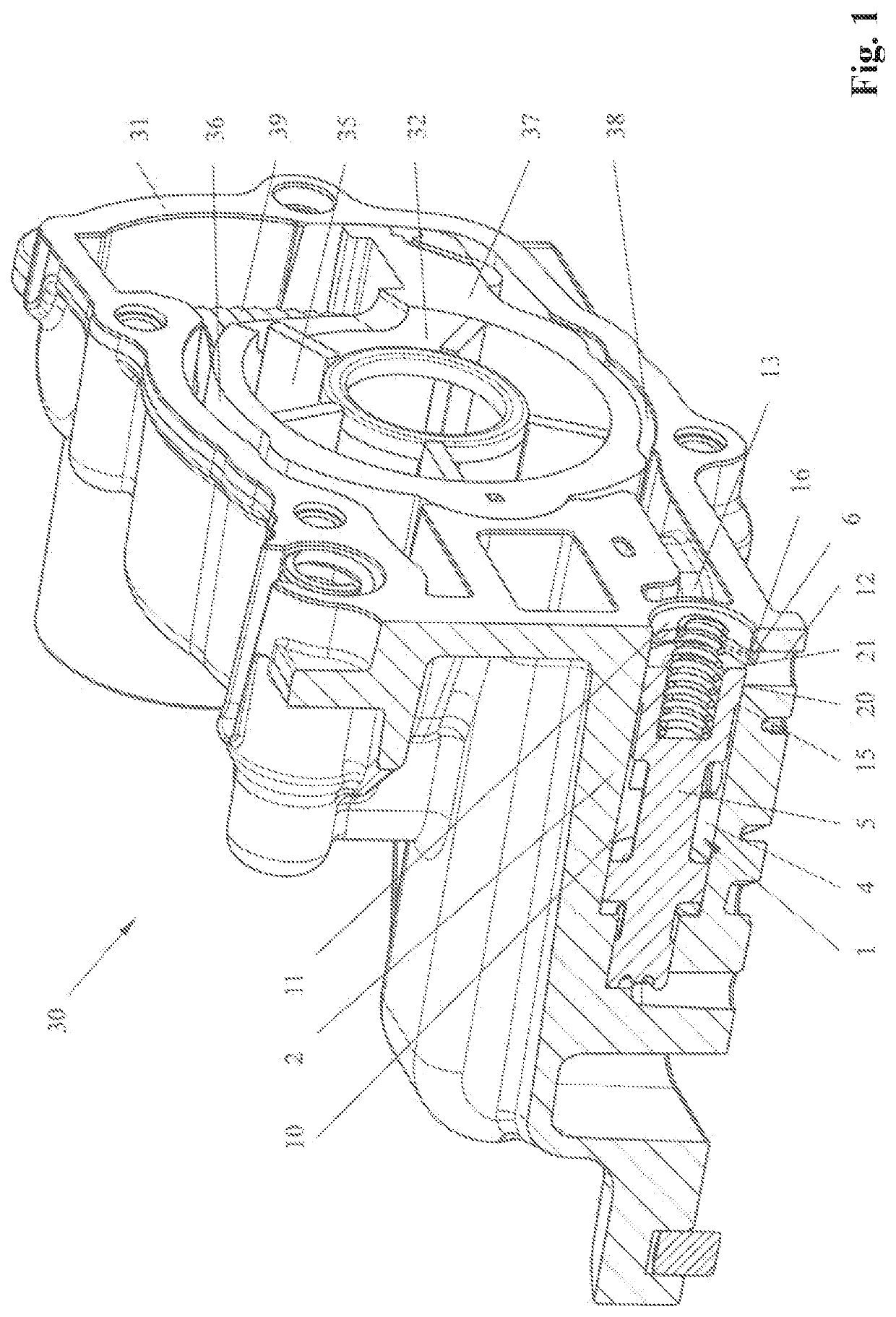
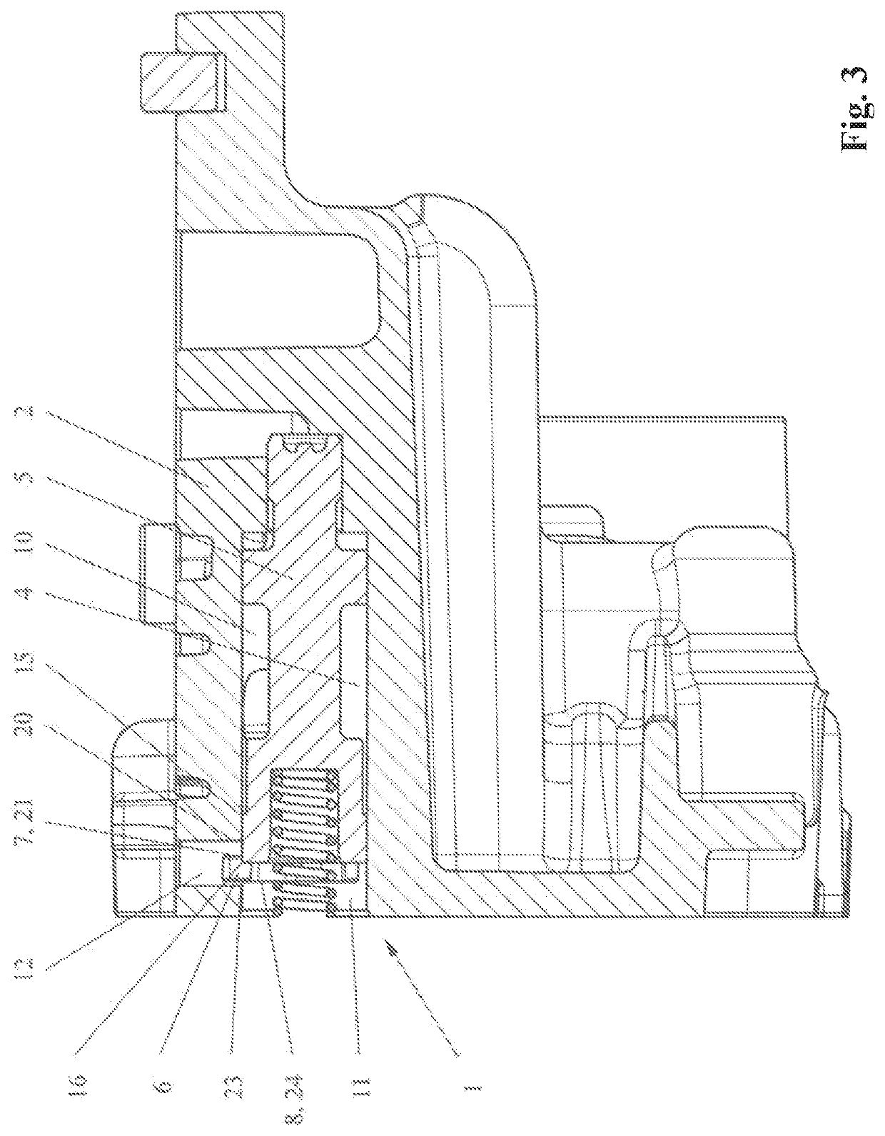
[0115]FIG. 1 shows a perspective sectional representation of an example embodiment of a pump 30 comprising a control valve 1 in accordance with the invention.

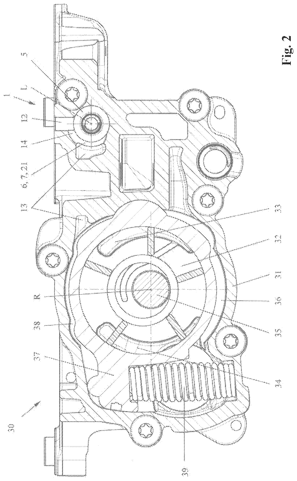
[0116]The pump 30 is embodied as a rotary pump 30, in particular a vane cell pump 30, and comprises a pump housing 31. The pump housing 31 delineates a pump chamber 36 in which a preferably pivotable adjusting member 37 and a rotatable delivery rotor 35 are arranged. The delivery rotor 35 comprises multiple vanes which are distributed across the circumference of the delivery rotor 35, wherein each two adjacent vanes respectively delineate a delivery chamber 32 together with the outer surface area of the delivery rotor 35 and the inner surface area of the adjusting member 37.

[0117]The adjusting member 37 can be pivoted within the pump chamber 36 such that the adjusting member 37 exhibits a variable eccentricity relative to the axis of rotation of the delivery rotor 35. The delivery volume of the pump 30 can be regulated via the ...


PUM


Abstract

A control valve for a pump for delivering a fluid. The control valve includes: a valve housing which delineates a piston chamber; a piston which can be moved within the piston chamber; and a fluid channel which ports into the piston chamber via a port opening, wherein the port opening defines a port control edge. The valve housing includes a recess which extends into the fluid channel, wherein the recess defines a recess control edge which is axially offset with respect to the port control edge, and / or the piston includes a piston recess which defines a piston recess control edge.

Description

CROSS REFERENCE TO RELATED APPLICATION[0001]This application claims benefit of priority from German Patent Application 10 2021 101 830.7, filed Jan. 27, 2021. The contents of this application are incorporated herein by reference.FIELD OF THE INVENTION[0002]The present invention relates to a control valve for a pump and to a pump comprising such a control valve. The control valve comprises a valve housing which delineates a piston chamber. A movable piston is arranged within the piston chamber. Preferably, the piston can be moved back and forth along its longitudinal axis. The control valve also comprises a fluid channel which ports into the piston chamber via a port opening. The port opening defines a port control edge of the control valve.BACKGROUND OF THE INVENTION[0003]The prior art discloses control valves which comprise a piston featuring a piston control edge. Depending on its position, the piston closes or opens a port opening of a fluid channel of the control valve, wherein ...

Claims


Application Information

Patent Timeline
Patent Type & Authority Applications(United States)
IPC IPC(8): F15B13/042F04B49/00F04B49/08F04B49/24F04C14/24F16K11/07F16K17/10
CPCF15B13/042F04B49/002F04B49/08F16K31/1221F04C14/24F16K11/0716F16K17/105F04B49/24F04C14/16F04C14/22F04B53/10F04B7/04F04C2/344F15B13/02F16K27/041
Inventor KÜCHLE, STEFANTONTSCH, THOMASSCHILLING, SIMONE
Owner SCHWABISCHE HUTTENWERKE AUTOMOTIVE CMBH
Learn More