Controllable solenoid valve

a solenoid valve and control technology, applied in the direction of valve details, valve operating means/releasing devices, mechanical equipment, etc., can solve the problems of reducing the flow cross section between the connection openings, requiring more effort, and disturbing the noise and rebound of the valve, so as to prolong the cylindrical interior, reduce the noise and rebound, and avoid leakage.

Active Publication Date: 2006-03-09
RAUSCH & PAUSCH
View PDF3 Cites 12 Cited by
  • Summary
  • Abstract
  • Description
  • Claims
  • Application Information

AI Technical Summary

Benefits of technology

[0007] In the throttling range, the magnet of the solenoid valve is acting against a relatively stiff spring (ca. 5 to 20 N / mm). The value of electric current supplied to the solenoid valve determines the position of the valve locking body or sealing body. Basically, the components can be arranged in such a way that in the non-energized state of the electromagnet the connection between two connection openings of the solenoid valve is either opened or closed. If for a corresponding valve the connection of the two connection openings is opened in the non-energized state of the electromagnet and the pressure spring has its maximum possible extension, the slide or piston connected to the solenoid armature closes radial-oriented passages (boreholes, long holes, etc.) with the current increasing. Thus, the flow cross section between the connection openings is reduced. The throttle effect increases and the cylinder movement is specifically influenced. At the end of the control range, only gap leakages between the two connection openings are possible. This invention also includes the options to close only one passage or different passages in a cylindrical housing by means of the slide.
[0008] For the process just described, the slide moves within the cylindrical interior of a housing of a solenoid valve, which can preferably be a 3 / 2 or 2 / 2 solenoid valve. At one end of this valve, the electromagnet is positioned and at its other end a pump connection is installed prolonging the cylindrical interior. For a fixed, maximum switching current, the solenoid drive of the slide overcomes the pressure forces at the pump connection and thus it connects the pump connection and the radial connection opening in the housing located most closely to it. At the same time, the communication between the two radial connection openings is interrupted by another sealing element in such a way that even leakages are avoided. Then, a triggered cylinder can be moved towards the opposite direction.
[0009] According to the invention, the control function is achieved without needing additional solenoid valves and with the minimum possible space requirements. It ensures a high grade of reproducibility for the manufacturing process and a simple replacement for retrofitting purposes. Even for devices that have already been installed, modifications or optimizations of the movement sequences only require the adjustment of the electric or electronic trigger action. Adjustments and fine adjustments can be made during the manufacturing process by means of an adjuster provided at the slide. The electrically adjustable throttling allows various applications of the invention for control tasks waiting to be solved as a far as a solenoid valve is used.

Problems solved by technology

Said forces lead to unwanted high movement speeds and cause the top to slide into the end stops without being slowed-down, thus causing disturbing noise and rebounds.
Moreover, the adjustment of the hydraulic throttles is a time-consuming and labor-intensive process, because the components produced cannot be modified later.
This development leads to the most expensive variant and involves the risk of mix-ups in the production process; thus, it will require more efforts.

Method used


Image

  • Controllable solenoid valve
  • Controllable solenoid valve
  • Controllable solenoid valve

Examples


Embodiment Construction

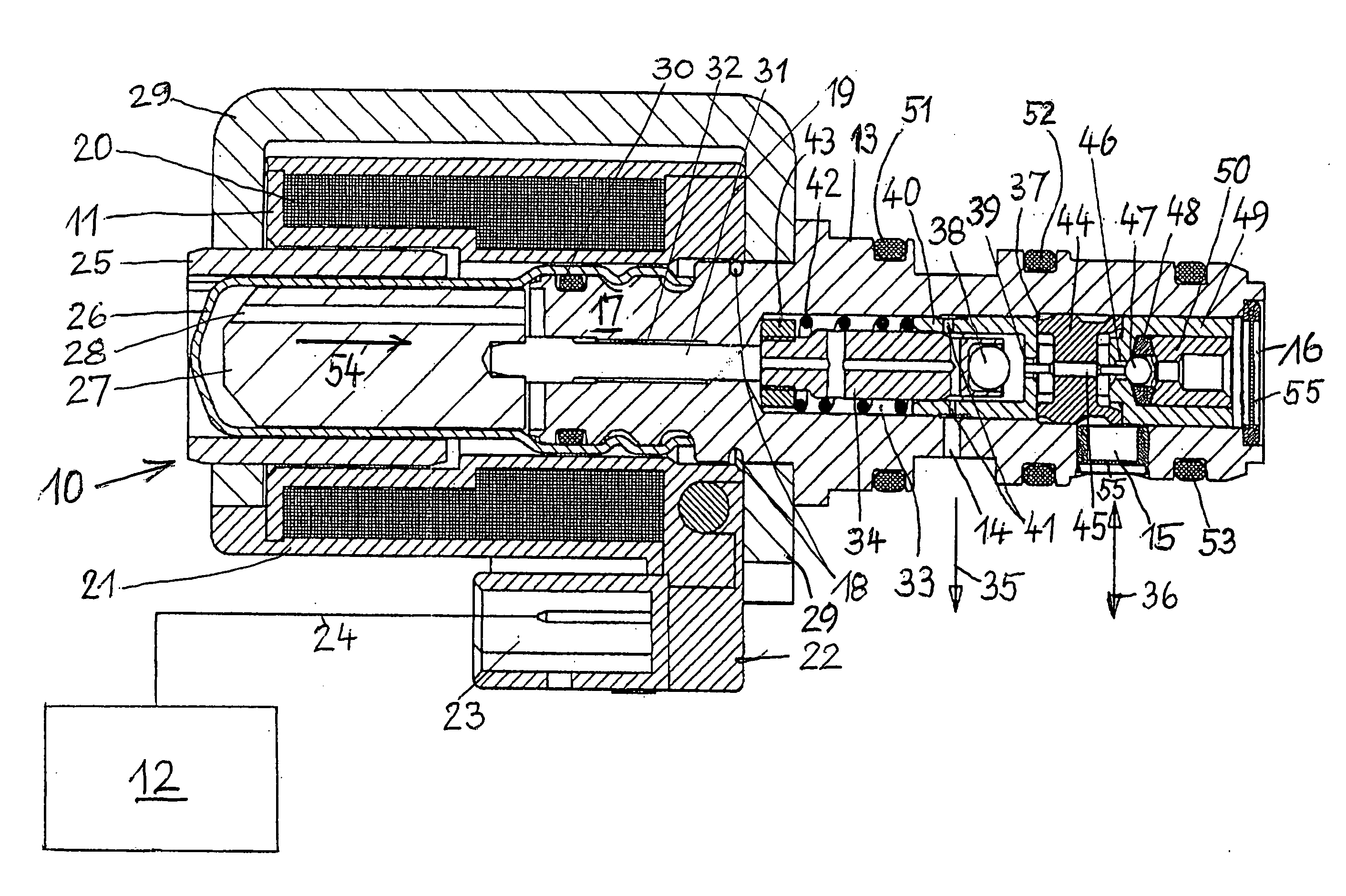
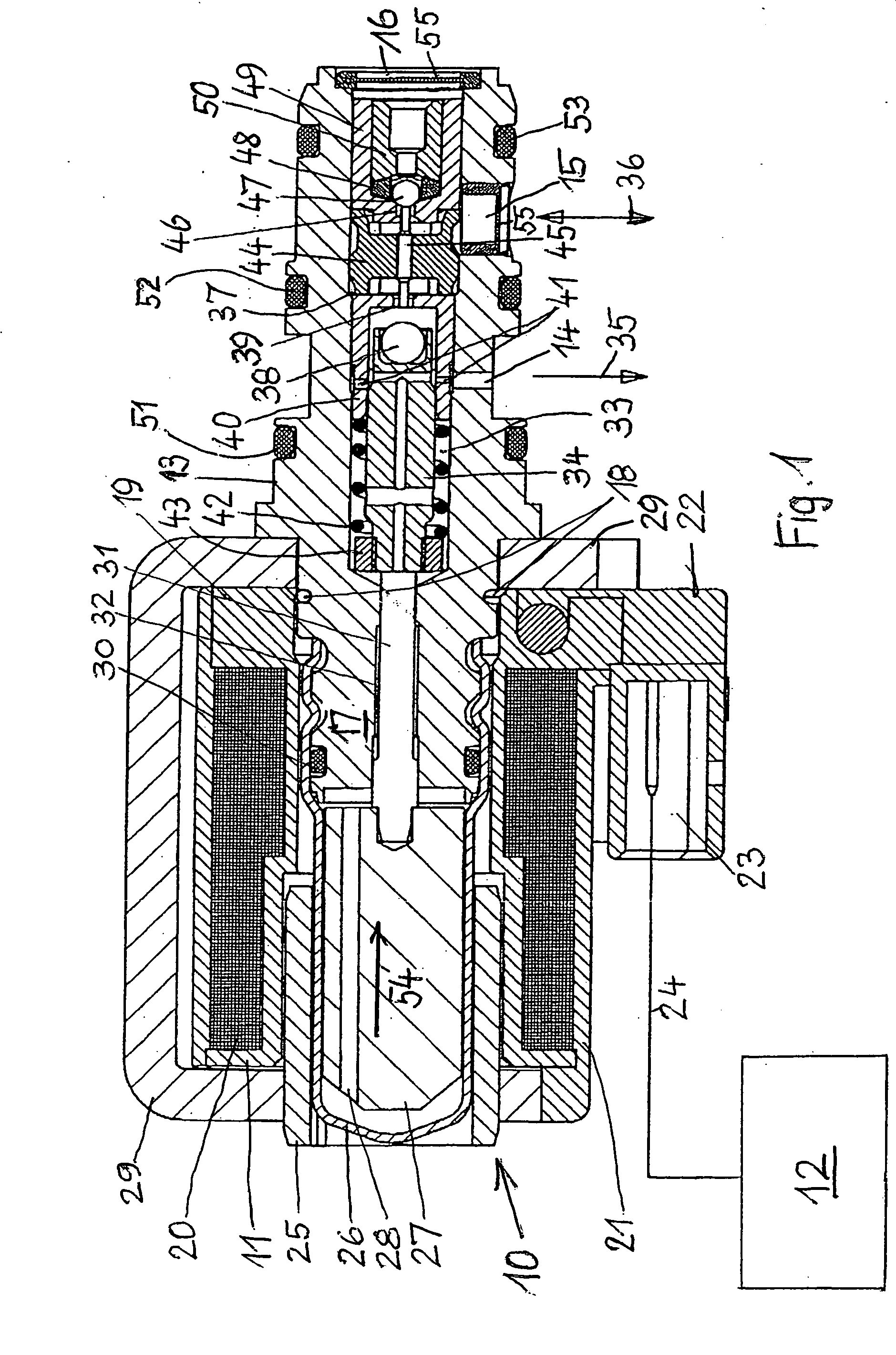
[0020]FIG. 1 shows a solenoid valve 10 which principally consists of an electromagnet 11 with an electric control unit 12 and a housing 13 provided with connection openings 14, 15 as well as a connection 16. One end 17 of the housing 13 located opposite to the connection 16 projects into the electromagnet 11 and is fixed to it by pins 18 or screws. The two components 11 and 13 could also be connected with each other by a screwed joint.

[0021] The electromagnet 11 is a wire-wound coil 20 the wire of which is wound around a hollow winding body 19 made of insulation material. If an electric current flows through the coil 20, the coil generates a magnetic field that depends on the value of this current flow. Along its circumference, the coil 20 is provided with an electrically insulating and heat-dissipating extrusion coating 21. At one terminal 22 of the winding body 19, a plug-type connector 23 is provided for a line 24 leading to the electric control unit 12 that supplies a current o...


PUM


Abstract

Controllable solenoid valve in which, due to the interaction between a magnetic force caused by an electrical flow and a spring force acting against the magnetic force, at least one first sealing body in the interior of a valve housing is displaced in axial direction between two final positions whereby moving relative to its first sealing seat. The interior extends from one electromagnet to a connection. To enable, in a simple manner, a specific reproducible influencing of the sequence speed of cylinder controls in hydraulic drives and to prevent uncontrolled movements by these drives, the first sealing seat up to the first sealing body is provided with an axially extending cylindrical housing inside of which a slide is axially displaced according to the electrical flow. The cylindrical housing comprises radially oriented passages, whereby these passages are closed if the first sealing body is located in a final position in its first sealing seat or in the immediate vicinity of the first sealing seat, and the passages are opened if the first sealing body is located in the opposite final position.

Description

BACKGROUND OF THE INVENTION [0001] The invention relates to a controllable solenoid valve according to the species of the patent claims. These kinds of valves are used in such applications that intend to influence the sequence speed of cylinder controls in hydraulic drives, in particular in automatic convertible tops. [0002] For the control of convertible top sequences, 3 / 2 solenoid valves are used in poppet design which are for example described in DE 3722344 A1. To prevent refluxes, an additional check valve can be installed at the pump connection or partly integrated into the solenoid seat valve, see EP 0 565 190 A1. In practical applications, weights and cinematic forces determine the movement sequences. In certain positions the own weight of the top already causes a movement. Said forces lead to unwanted high movement speeds and cause the top to slide into the end stops without being slowed-down, thus causing disturbing noise and rebounds. [0003] In vehicles, spring or buffer e...

Claims


Application Information

Patent Timeline
Patent Type & Authority Applications(United States)
IPC IPC(8): F15B13/044F15B13/01F15B13/04F16K31/06
CPCF15B13/01F15B13/0402F16K31/0637F15B13/0442F15B13/0405Y10T137/87241F15B2211/20538F15B2211/50536F15B2211/7052F16K31/062
Inventor DOCHLA, WERNERRAUCH, MICHAEL
Owner RAUSCH & PAUSCH
Why Eureka
Try Eureka