Controllable oil separation device

An oil separation and equipment technology, applied in the field of controllable oil separation equipment, can solve the problem of not being able to improve separation performance, and achieve the effects of small overall size, improved separation performance, and improved efficiency

Active Publication Date: 2016-06-22
THYSSENKRUPP PRESTA TECCENTER AG
View PDF9 Cites 8 Cited by
  • Summary
  • Abstract
  • Description
  • Claims
  • Application Information

AI Technical Summary

Problems solved by technology

If the volume flow of oily gas decreases again, the individual flow cross-sections of the cyclone are closed again, but even with this system the flow energy for throttling cannot be successfully used to increase the separation performance

Method used


Image

  • Controllable oil separation device
  • Controllable oil separation device
  • Controllable oil separation device

Examples


Embodiment Construction

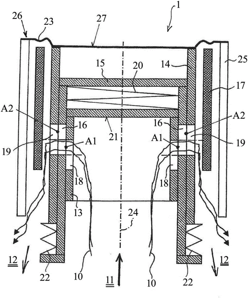
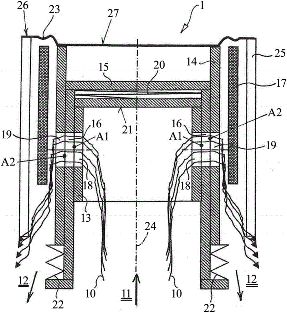
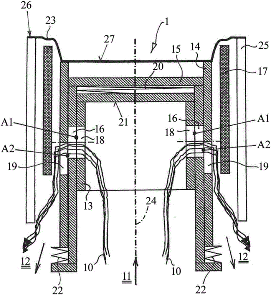
[0028] exist Figure 1 to Figure 4c In , features with the same technical function and effect are denoted by the same reference numerals.

[0029] Figure 1 to Figure 4c Each of these shows an embodiment of the oil separation device 1 in various operating states corresponding to various operating moments of the internal combustion engine. Therefore firstly the description is independent of the operating state according to Figure 1 to Figure 4c The configuration of the oil separation device 1 illustrated in .

[0030] The oil separation device 1 serves to separate oil from an air flow 10 which ventilates the crankcase of an internal combustion engine. For this purpose, the oil separation device 1 has an inflow side 11 which can be fluidically connected to the crankcase of the internal combustion engine. The oil separation device 1 also has an outflow side 12 which can be connected to the intake duct of the internal combustion engine.

[0031] The oil separation device 1 h...


PUM


Abstract

The invention relates to an oil separation device (1) for separating oil from an air flow (10) for ventilating the crankcase of an internal combustion engine, said device having an inflow side (11) and an outflow side (12), the inflow side (11) can be fluidly connected to a crankcase of an internal combustion engine and an oil-containing gas stream (10) can flow from said inflow side (11) to an oil separation device (1), said outflow side (12) can be fluidly connected to an intake channel of an internal combustion engine and substantially An oil-cleared gas stream (10) can flow from the oil separation device (1) to said outflow side. According to the invention, a first control member (13) is provided, by means of which a first flow cross-section (A1) of the gas flow (10) through the oil separation device (1) can be varied and by means of the crankshaft The gas pressure in the tank controls the first member and provides a second control member (14) through which a second flow cross-section (A2) of the gas flow (10) through the oil separation device (1) can pass ( 14) The second component varies and can be controlled by a pressure drop in the intake channel, the second flow cross-section (A2) being located downstream of the first flow cross-section (A1).

Description

technical field [0001] The invention relates to an oil separation device for separating oil from a gas flow that ventilates the crankcase of an internal combustion engine, said device having an inflow side and an outflow side, said inflow side being fluidly connectable to the crankcase of an internal combustion engine and from which the oil-laden gas flow can flow Said inflow side flows to an oil separation device, said outflow side may be fluidly connected to an intake channel of an internal combustion engine and a substantially oil-free gas flow may flow from the oil separation device to said outflow side. Background technique [0002] In the case of the use of non-switchable oil separation devices for separating oil from the gas flow that ventilates the crankcase of an internal combustion engine (known as "air flow purge"), the flow geometry associated with oil separation generally does not follow the Purge application volume flow varies. Therefore, oil separation equipm...

Claims


Application Information

Patent Timeline
Patent Type & Authority Applications(China)
IPC IPC(8): F01M13/00F01M13/02F01M13/04
CPCF01M13/04B01D45/08F01M13/00F01M13/022F01M13/023F01M2013/0005F01M2013/0044F01M2013/0433
Inventor U·穆勒
Owner THYSSENKRUPP PRESTA TECCENTER AG
Why Eureka
Try Eureka