Ventilating fan provided with linkage type air valve

A tuyere valve and ventilation fan technology, which is applied to non-variable-capacity pumps, machines/engines, pump control, etc., can solve problems such as the inability to close the vents and the inability to achieve air flow in the air duct, and avoid poor interception effect and increase. The effect of air velocity

Active Publication Date: 2017-10-10
SICHUAN COLLEGE OF ARCHITECTURAL TECH
View PDF11 Cites 8 Cited by
  • Summary
  • Abstract
  • Description
  • Claims
  • Application Information

AI Technical Summary

Problems solved by technology

[0006] The purpose of the present invention is to provide a ventilating fan with a linkage type tuyere valve, which is used to solve the problem that the existing ventilating fan cannot adjust the air flow of the air duct from zero to the maximum value, resulting in that when the ventilating needs to be stopped, the existing ventilating fan cannot Problems with effective closure of vents

Method used


Image

  • Ventilating fan provided with linkage type air valve
  • Ventilating fan provided with linkage type air valve
  • Ventilating fan provided with linkage type air valve

Examples


Embodiment 1

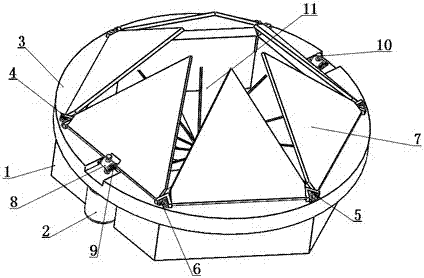
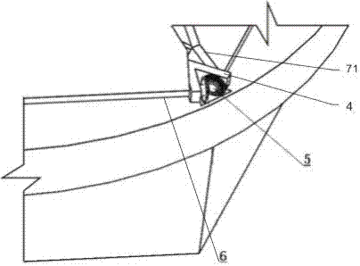
[0027] combined with Figure 1-3 As shown, a ventilation fan with a linkage type tuyere valve includes a body 1 with a regular hexagonal or circular cross section. The direction is the same, any end of the body 1 along the axial direction is fixedly connected with a ring-shaped fixed ring 3, and the fixed ring 3 is provided with a six-leaf linkage tuyere valve with a stabilizing effect, and the tuyere valve includes Relative to the six equilateral triangular baffles 7 installed on the upper surface of the fixed ring 3, the baffles 7 are hinged to the mounting seat 4 arranged on the fixed ring 3, and the bottom edge of the baffles 7 is fixed A rotating shaft 6 welded parallel to the bottom is connected, and the two ends of the rotating shaft 6 pass through the mounting seat 4 and are connected with a bevel gear 5, and the bevel gears 5 at the two ends of the adjacent two interceptor plates 7 mesh with each other; wherein, Two parallel rocker arms 9 are fixedly installed in the...

Embodiment 2

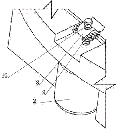
[0031] In order to further realize the present invention, on the basis of Embodiment 1, further, this embodiment adopts the following settings: the lifting mechanism includes a drive motor 2 that is detachably and fixedly connected to the lower surface of the fixed ring 3 The drive shaft of the drive motor 2 runs through the fixed ring 3 and the drive shaft of the protruding part is provided with external threads, the drive shaft is threaded with a push-pull block 8, and the two ends of the push-pull block 8 are integrally connected with a rocker along the length direction. Rod, the rocking rod is inserted in the bar-shaped hole provided along the length direction of the rocking arm 9 and the diameter of the rocking rod is smaller than .

[0032] Working principle: When the lifting mechanism needs to rise, the drive motor 2 rotates forward, and the push-pull block 8 rises along the drive shaft under the thread cooperation of the drive shaft. During the rising process, the push-...

Embodiment 3

[0034] In order to further realize the present invention, on the basis of Embodiment 1, further, this embodiment particularly adopts the following settings: the lifting mechanism includes a lifting rod hinged with the free end of the rocker arm 9, and the lifting The rod runs through the fixed ring 3 and is driven and connected to the drive motor 2 fixedly installed on the lower surface of the fixed ring 3. The elevating rod is provided with a rack, and the rack is meshed with the gear on the drive shaft of the drive motor 2. By driving The forward and reverse motion of the motor 2 drives the elevating rod to move up and down, so as to realize the purpose of controlling the free end of the rocker arm 9 to swing up and down. Because the rocker arm 9 and the cutoff plate 7 are fixedly connected, the purpose of controlling the cutoff plate 7 is achieved. The specific structure of the free end of the rocking arm 9 hinged lifting rod described in this embodiment is: the rocking arm ...


PUM


Abstract

The invention discloses a ventilating fan provided with a linkage type air valve. The ventilating fan comprises a body and a ventilating fan part; the body is fixedly connected with a fixing ring along any end in the axial direction; the fixing ring is provided with a six-vane linkage type air valve which plays a flow stabilization effect; the air valve comprises six equilateral-triangle-shaped intercepting plates which are oppositely installed at the upper surface of the fixing ring; the intercepting plates are articulated with a mounting base; the bottom side of each intercepting plate is fixedly connected with a rotating shaft; the two ends of each rotating shaft are connected with conical gears after penetrating through the mounting base; the conical gears at the two ends of two adjacent intercepting plates are meshed with each other, wherein two parallel rocker arms are fixedly installed at the middle part of each rotating shaft at the bottom side of any intercepting plate; and a lifting mechanism for making each intercepting plate do reciprocating rotation by taking the rotating shaft at the bottom side as the circle center is installed between the two rocker arms. According to the ventilating fan disclosed by the invention, by the linked intercepting plates, the angle of each intercepting plate with respect to a vent can be adjusted through the lifting mechanism so as to realize different degrees of obstruction to the vent, and the aim of regulating the air flow is realized.

Description

technical field [0001] The present invention relates to the field of ventilation or air intake and exhaust devices, in particular to the field of duct ventilation devices and indoor ventilation devices, in particular to a ventilation fan with a linkage type tuyere valve. Background technique [0002] Ventilation fan is a very common and commonly used ventilation device. It is usually used for indoor and outdoor air exchange, or for air exhaust in places such as kitchens. Although there are many types of ventilation fans, they usually use motor-driven impellers. Rotate to discharge the air by suction to achieve the purpose of exchanging air. There is also an air duct air drive for long-distance ventilation, but the existing ventilation fans usually can only obtain different speeds of the drive motor by changing the current of the ventilation fan driving motor. The disadvantage of this setting is that when ventilation is not required , the existing ventilating fan can't block...

Claims


Application Information

Patent Timeline
Patent Type & Authority Applications(China)
IPC IPC(8): F04D25/08F04D27/00
CPCF04D25/08F04D27/003
Inventor 严珍凤谢明阳
Owner SICHUAN COLLEGE OF ARCHITECTURAL TECH
Why Eureka
Try Eureka