Engine encapsulation structure of vehicle

a technology of engine and encapsulation structure, which is applied in the direction of machines/engines, mechanical equipment, transportation and packaging, etc., can solve the problems of limited improvement effect and range in the synthetic terms of the engine room, and the difficulty of achieving sufficient effect in terms of overall engineering performance of the engine room and in the synthetic side, so as to improve cooling performance and improve relating performance.

Active Publication Date: 2015-04-28
HYUNDAI MOTOR CO LTD +1
View PDF19 Cites 8 Cited by
  • Summary
  • Abstract
  • Description
  • Claims
  • Application Information

AI Technical Summary

Benefits of technology

[0014]Various aspects of the present invention are directed to providing a multipurpose engine encapsulation structure of a vehicle that can simultaneously improve relating performance, such as fuel efficiency, acoustics, and aerodynamics, by optimizing heat flow in an engine room for improving cooling performance and by optimizing heat management in the engine room.
[0024]A nozzle throat forming portion that accelerates air by reducing a flow cross-sectional area of the air discharged through the rear outlet is additionally formed at a rear portion of an underside cover of the underbody encapsulation member.
[0030]Therefore, according to the engine encapsulation structure of a vehicle, the structure covers the engine and the transmission and has a performance of blocking heat, such that it is possible to rapidly warm up the engine and the transmission at the next early stage of driving by keeping the heat in the engine room, and to contribute to improving fuel efficiency by reducing mechanical friction force.
[0031]In particular, the engine encapsulation structure of the present invention makes it possible to reduce exhaust gases, such as CO2, improve initial fuel efficiency, improve initial heating performance, and reduce wear of the engine and the transmission by reducing the warming-up time, and to have a sound-absorbing performance with reduction of cold idle noise, such that it provides an advantage of reducing noise (engine noise and road noise while driving) transmitted into the interior through a dash panel and reducing damage to pedestrians because the structure functions as a shock-absorbing structure when hitting a pedestrian.

Problems solved by technology

However, although it is possible to improve partial performance, such as cooling an engine and preventing thermal damage, but it is difficult to achieve sufficient effect in terms of overall engineering performance of the engine room and in the synthetic side, such as fuel efficient or emission, acoustics, and aerodynamics, only by optimizing the heat flow for the layout of the engine room.
Further, a desired effect for improving cooling performance and efficient by optimizing the structure and arrangement of a cooling module (for example, tilting a cooling fan), applying an active air flap, and optimizing the arrangement and structure of an air guide in the related art, but in practice, the improvement effect and range are limited in the synthetic terms of the engine room and there is a limit to distributing heat flow to the right positions due to complicated flow characteristics in the engine room.
Further, although the engine rooms are equipped with an engine cover that covers the upper portion of an engine and an under-cover that disposed at the lower portion of the engine room in common vehicles in order to reduce noise, the structure has been improved and optimized and the material has been improved for the parts in order to reduce noise and discharge heat, but fuel efficiency or aerodynamics has not been appropriately considered.

Method used


Image

  • Engine encapsulation structure of vehicle
  • Engine encapsulation structure of vehicle
  • Engine encapsulation structure of vehicle

Examples


Embodiment Construction

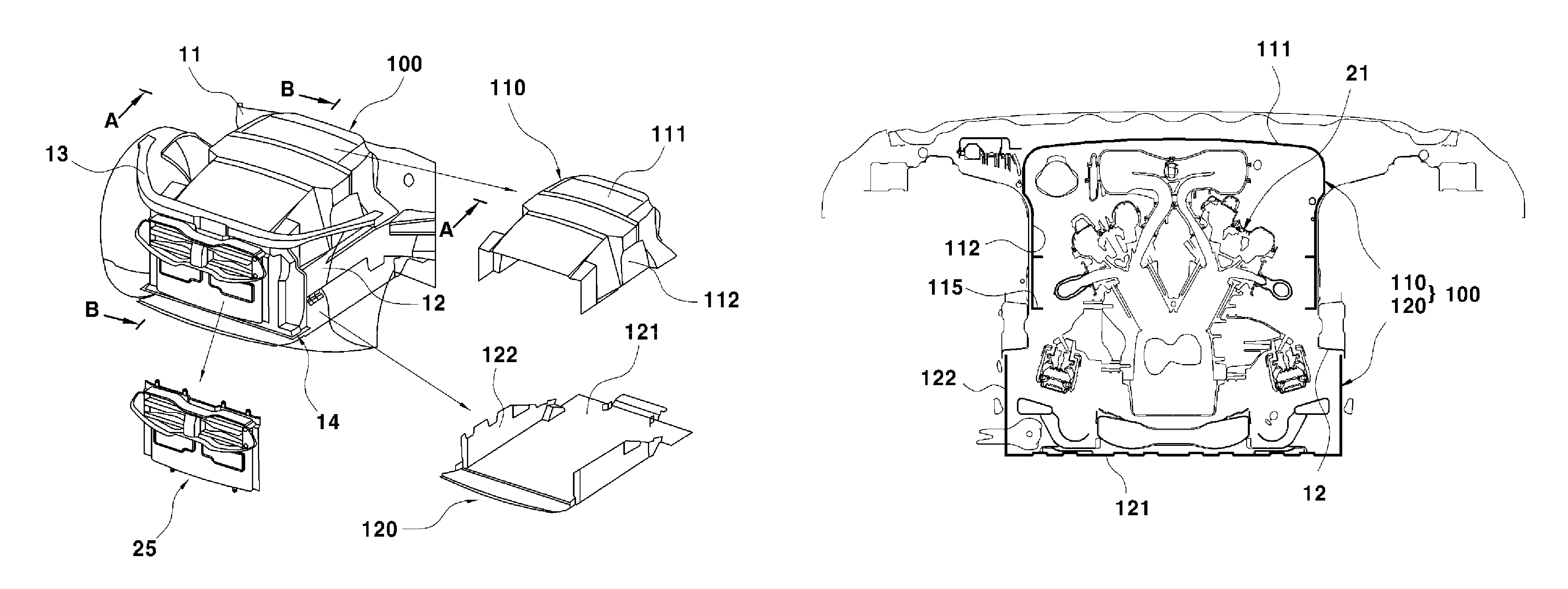
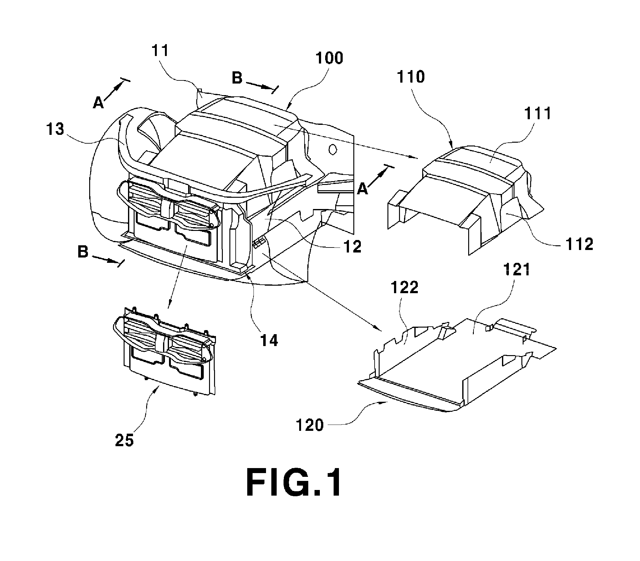
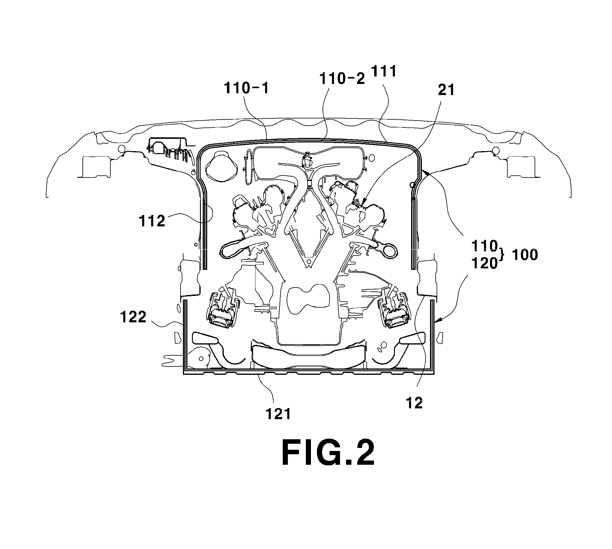
[0043]Reference will now be made in detail to various embodiments of the present invention(s), examples of which are illustrated in the accompanying drawings and described below. While the invention(s) will be described in conjunction with exemplary embodiments, it will be understood that the present description is not intended to limit the invention(s) to those exemplary embodiments. On the contrary, the invention(s) is / are intended to cover not only the exemplary embodiments, but also various alternatives, modifications, equivalents and other embodiments, which may be included within the spirit and scope of the invention as defined by the appended claims.

[0044]It is understood that the term “vehicle” or “vehicular” or other similar term as used herein is inclusive of motor vehicles in general such as passenger automobiles including sports utility vehicles (SUV), buses, trucks, various commercial vehicles, watercraft including a variety of boats and ships, aircraft, and the like, a...


PUM


Abstract

An engine encapsulation structure of a vehicle may include an engine room encapsulation member disposed at an upper portion of an engine compartment and covering an upper portion of a power train having an engine and a transmission, an underbody encapsulation member disposed at a lower portion of the engine compartment and covering a lower portion of the power train, wherein the engine room encapsulation member and the underbody encapsulation member form an inner space and enclose the power train in the inner space when being assembled each other, and a front inlet formed at a front portion of the assembly to allow air through the front inlet and to cool the power train while the air passes through the inner space of the assembly, the air being discharged through a rear outlet formed to the assembly.

Description

CROSS-REFERENCE TO RELATED APPLICATION[0001]The present application claims priority to Korean Patent Application No. 10-2011-0130150 filed Dec. 7, 2011, the entire contents of which is incorporated herein for all purposes by this reference.BACKGROUND[0002]1. Field of the Invention[0003]The present invention relates to an engine encapsulation structure of a vehicle. More particularly, it relates to a multipurpose engine encapsulation structure of a vehicle that can simultaneously improve relating performance, such as fuel efficiency, acoustics, and aerodynamics, by optimizing heat flow in an engine room for improving cooling performance and by optimizing heat management in the engine room.[0004]2. Description of Related Art[0005]A vehicle is structurally divided into a car body and a chassis. The car body is a part that forms the outer shape of the vehicle, including an engine room, and generally, an engine, a transmission, a cooling system, and various auxiliary components are dispo...

Claims


Application Information

Patent Timeline
Patent Type & Authority Patents(United States)
IPC IPC(8): B60K11/04B60K11/08B60K11/06
CPCB60K11/06B60K11/085F02B77/00F02B77/11
Inventor NAM, JONG WOOKIM, WON SIKCHUNG, HAN SHINOH, MIN SOOKIM, JAE YEONLEE, JONG HOON
Owner HYUNDAI MOTOR CO LTD
Why Eureka
Try Eureka