

Image formation apparatus and method of control
- Summary
- Abstract
- Description
- Claims
- Application Information
AI Technical Summary
Benefits of technology
Problems solved by technology
Method used
Image

Examples
example operation
of Execution Button
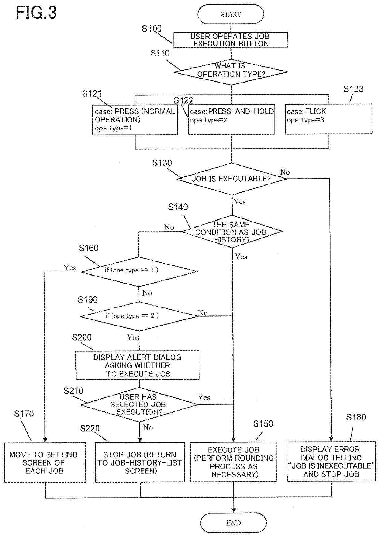
[0039]There are three kinds of example operation of the execution button in the operation unit 2, as follows.
1. For Normal Button Press (Excluding a Press-and-Hold and a Flick)
[0040]Execute a job immediately in response to no change in a job setting condition detected from a job history
[0041]Move to the setting screen of each job listed in the history in response to a change detected in the job setting condition
2. For Button Press-and-Hold
[0042]Execute the job immediately in response to no change in the job setting condition detected from the job history
[0043]Display an alert dialog asking whether to immediately execute the job when the job is executable, even in response to a change detected in the job setting condition; in addition, whether to move to the setting screen may be selected.
3. For Button Flick
[0044]Execute the job immediately in response to no change in the job setting condition detected from the job history
[0045]Execute a job forcedly even in respon...
example 1
[0069]Example 1 is an instance where a copy job is executed, followed by another job at a later date by reusing the history of the previous copy job.
Copy Job Execution
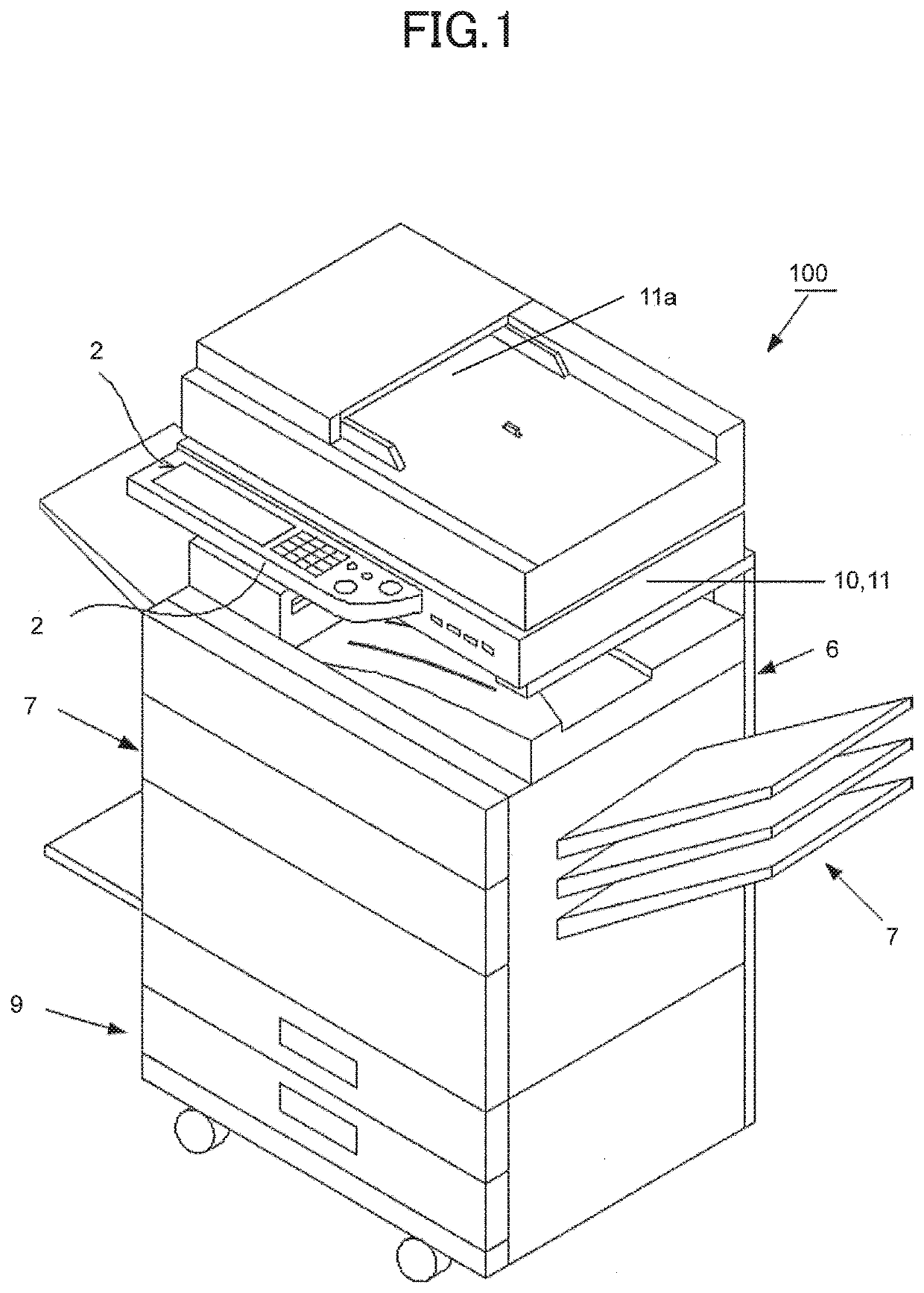
[0070]The user executed the following copy job via a copy mode screen of the setting screen 30 illustrated in FIG. 4. The settings for the copy job were what are shown in the copy setting region 30a of the setting screen 30 in FIG. 4 as follows: SPF duplexing (three A4-sized documents); for an item “tray”, an auto-paper-selection (APS) mode; for an item “stapling”, ON; for an item “the number of copy sets”, two; and color printing.
[0071]The user executed the copy job, where three A4-sized paper sheets underwent duplexing, followed by stapling together as a set, and two sets of the stapled sheets were output.
[0072]The multifunction printer 100 recorded the job as a history.
Execution Based on Job History
[0073]At a later data, the user placed two A3-sized documents on the SPF and operated a button for executing the forego...
example 2
[0092]Example 2 is an instance where a copy job is executed on the basis of the job history in Example 1 with the staples exhausted.
[0093]The user placed five A4-sized documents on the SPF and operated the button for executing the job history described in Example 1. The user operated the execution button through three kinds of operations 1 to 3: a normal press, a press-and-hold, and a flick.
1. For Normal Press on Execution Button (Corresponding to S121)
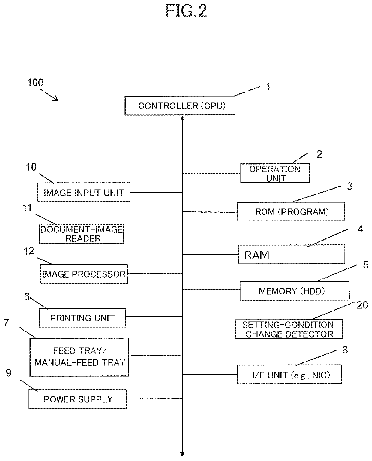
[0094]The staples were exhausted, and the setting-condition change detector 20 thus determined that the setting condition had changed (this corresponds to NO in S140).
[0095]The job was inexecutable under the job settings recorded in the history. Accordingly, a copy mode screen was displayed (this corresponds to YES in S160 and to S170).
[0096]The setting screen 30 in copy mode in this case displayed that the staples were exhausted, A display “No Staples” was shown in the copy setting region 30a illustrated in FIG. 5.
2. For Press-and-Ho...
PUM
 Abstract
Description
Claims
Application Information