Pneumatic tire

a technology of pneumatic tires and treads, applied in the field of pneumatic tires, can solve the problems of tire wear likely to suffer uneven wear, and achieve the effects of suppressing uneven wear, reducing lateral swaying of the vehicle, and increasing the rigidity of the tread portion

Pending Publication Date: 2022-09-15
THE YOKOHAMA RUBBER CO LTD
View PDF0 Cites 0 Cited by
  • Summary
  • Abstract
  • Description
  • Claims
  • Application Information

AI Technical Summary

Benefits of technology

[0004]The technology provides a pneumatic tire that can provide improved heat build-up resistance performance of the tire while maintaining uneven wear resistance performance of the tire.
[0006]In the pneumatic tire according to an embodiment of the technology, (1) the single center land portion is disposed, thus increasing the rigidity of a tread portion to reduce lateral swaying of the vehicle. This has the advantage of suppressing uneven wear caused by lateral swaying to improve uneven wear resistance performance of the tire. Additionally, (2) the center land portion comprises the plurality of center narrow shallow grooves extending through the center land portion, and thus there is an advantage that the cooling action of the center narrow shallow grooves improves the heat build-up resistance performance of the tire. Additionally, (3) there is an advantage that the above-described lower limit of the ratio H21 / Hg ensures the cooling action of the center narrow shallow grooves, whereas the above-described upper limit of the ratio H21 / Hg ensures the rigidity of the tread portion.

Problems solved by technology

For example, construction vehicle tires mounted on a port straddle carrier have a problem in that the tires are likely to suffer uneven wear due to lateral swaying of the mounting vehicle attributed to the high vehicle height of the mounting vehicle.

Method used


Image

  • Pneumatic tire
  • Pneumatic tire
  • Pneumatic tire

Examples


modified examples

[0070]FIGS. 8 to 10 are explanatory diagrams illustrating modified examples of the pneumatic tire illustrated in FIG. 2. In these drawings, constituents that are the identical to constituents illustrated in FIG. 2 have the identical reference signs, and explanations thereof are omitted.

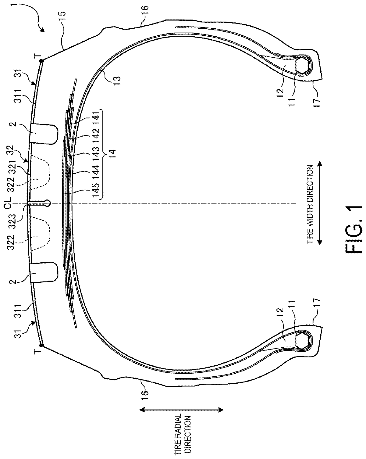
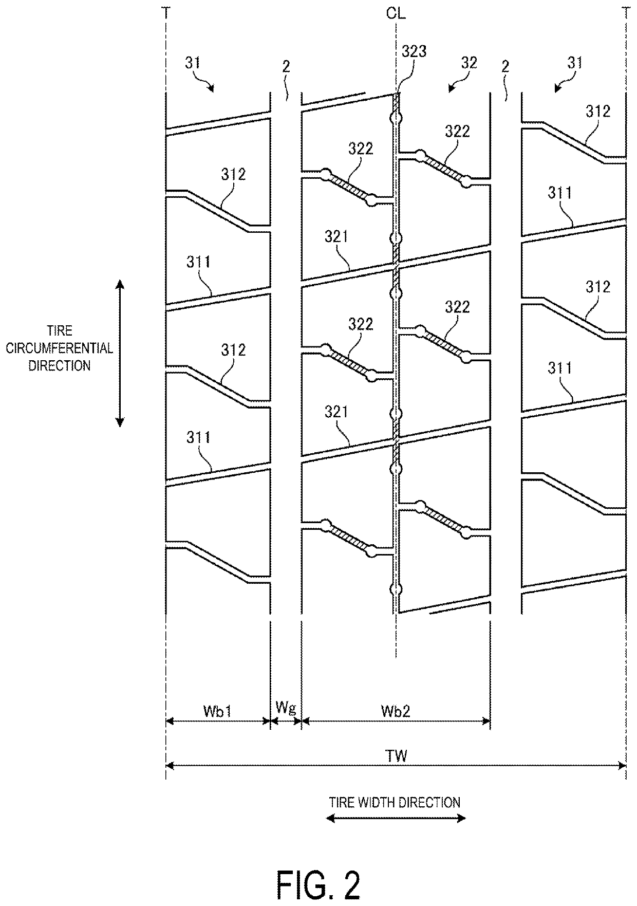
[0071]In the configuration of FIG. 2, as described above, the shoulder land portion 31 includes the plurality of shoulder narrow shallow grooves 311 and the plurality of shoulder bent grooves 312. In such a configuration, the shoulder narrow shallow grooves 311 and the shoulder bent grooves 312 effectively cool the tread contact surface to improve the heat build-up resistance of the tire.

[0072]However, no such limitation is intended, and as illustrated in FIG. 8, the shoulder narrow shallow grooves 311 and the shoulder bent grooves 312 may be omitted. In the configuration of FIG. 8, the shoulder land portion 31 includes no grooves but includes a road contact surface extending continuously in the tire ...

examples

[0091]FIGS. 11 and 12 are tables showing the results of performance tests of pneumatic tires according to embodiments of the technology.

[0092]In the performance tests, (1) heat build-up resistance performance and (2) uneven wear resistance performance were evaluated for a plurality of types of test tires. Additionally, the test tires having a tire size of 1600R25 are mounted on rims having a rim size of 25×11.25−2.0, and an internal pressure of 1000 kPa and 85% of a load specified by JATMA are applied to the test tires.

[0093](1) In the evaluation of heat build-up resistance performance, an indoor drum testing machine was used, and the amount of heat generated by the tire was measured after traveling at a speed of 25 km / h for four hours. The measurement results are expressed as index values and evaluated with Conventional Example being assigned as the reference (100). In this evaluation, larger values are preferable.

[0094](2) In the evaluation of uneven wear resistance performance, t...


PUM


Abstract

A pneumatic tire includes a pair of circumferential main grooves extending in a tire circumferential direction, and a pair of shoulder land portions and a single center land portion defined and formed by the circumferential main grooves. In addition, the center land portion includes a plurality of center narrow shallow grooves extending through the center land portion in a tire width direction. A groove depth H21 of the center narrow shallow groove is in a range 0.025≤H21 / Hg≤0.150 with respect to a maximum groove depth Hg of the circumferential main groove.

Description

TECHNICAL FIELD[0001]The technology relates to a pneumatic tire and particularly relates to a pneumatic tire that can provide improved heat build-up resistance performance of the tire while maintaining uneven wear resistance performance of the tire.BACKGROUND ART[0002]For example, construction vehicle tires mounted on a port straddle carrier have a problem in that the tires are likely to suffer uneven wear due to lateral swaying of the mounting vehicle attributed to the high vehicle height of the mounting vehicle. Thus, in order to enhance the uneven wear resistance performance of the tire, known construction vehicle tires employ a tread pattern including a pair of circumferential main grooves, and a pair of shoulder land portions and a single center land portion that are defined and formed by the circumferential main grooves. Construction vehicle tires employing the above-described configuration are known (see, e.g., Internet URLs (Uniform Resource Locators): https: / / www.michelinea...

Claims


Application Information

Patent Timeline
Patent Type & Authority Applications(United States)
IPC IPC(8): B60C11/13
CPCB60C11/13B60C2011/0348B60C11/03B60C11/00B60C11/0306B60C2011/0362B60C2011/036B60C2011/0369B60C2011/0367B60C2011/0365B60C2011/0355B60C2011/0353B60C2011/0372B60C2011/0351
Inventor MOTOMITSU, TAKAMASA
Owner THE YOKOHAMA RUBBER CO LTD
Why Eureka
Try Eureka