Heat-assisted magnetic recording (HAMR) head with tapered main pole and heat sink material adjacent the pole

a magnetic recording and heat sink technology, applied in the field of heat sink material adjacent the main pole and the heat sink head, can solve the problems of reducing the data rate and the main pole being easily oxidized at the gbs, and achieves the effects of increasing the rise time of the magnetic field, wide cross-track width, and high magnetic field

Active Publication Date: 2022-11-10
WESTERN DIGITAL TECH INC
View PDF13 Cites 0 Cited by
  • Summary
  • Abstract
  • Description
  • Claims
  • Application Information

AI Technical Summary

Benefits of technology

[0006]In conventional HAMR heads the main magnetic pole for generating the magnetic field for writing has a relatively wide cross-track width to apply a high magnetic field at the optical spot generated by the NFT. However, the wide main pole increases the rise time of the magnetic field during writing and thus decreases the data rate. Thus it is desirable to reduce the width of the main pole but without substantially decreasing the magnetic field applied at the optical spot. Additionally, the main pole is easily oxidized at the GBS due to temperature rise and wear of the protective overcoat on the head. Thus it is desirable to minimize oxidation of the main pole.
[0007]In embodiments of this invention, the main pole is formed of two layers, with the first layer having a width that tapers down in the direction towards the NFT where the optical spot is formed, and the second layer located away from the NFT having a substantially wider width than the first layer so as to provide sufficient magnetic field. Layers of heat sink material are located on the sloped cross-track sides of the tapered main pole first layer to reduce the temperature and thus the likelihood of oxidation.

Problems solved by technology

However, the wide main pole increases the rise time of the magnetic field during writing and thus decreases the data rate.
Additionally, the main pole is easily oxidized at the GBS due to temperature rise and wear of the protective overcoat on the head.

Method used


Image

  • Heat-assisted magnetic recording (HAMR) head with tapered main pole and heat sink material adjacent the pole
  • Heat-assisted magnetic recording (HAMR) head with tapered main pole and heat sink material adjacent the pole
  • Heat-assisted magnetic recording (HAMR) head with tapered main pole and heat sink material adjacent the pole

Examples


Embodiment Construction

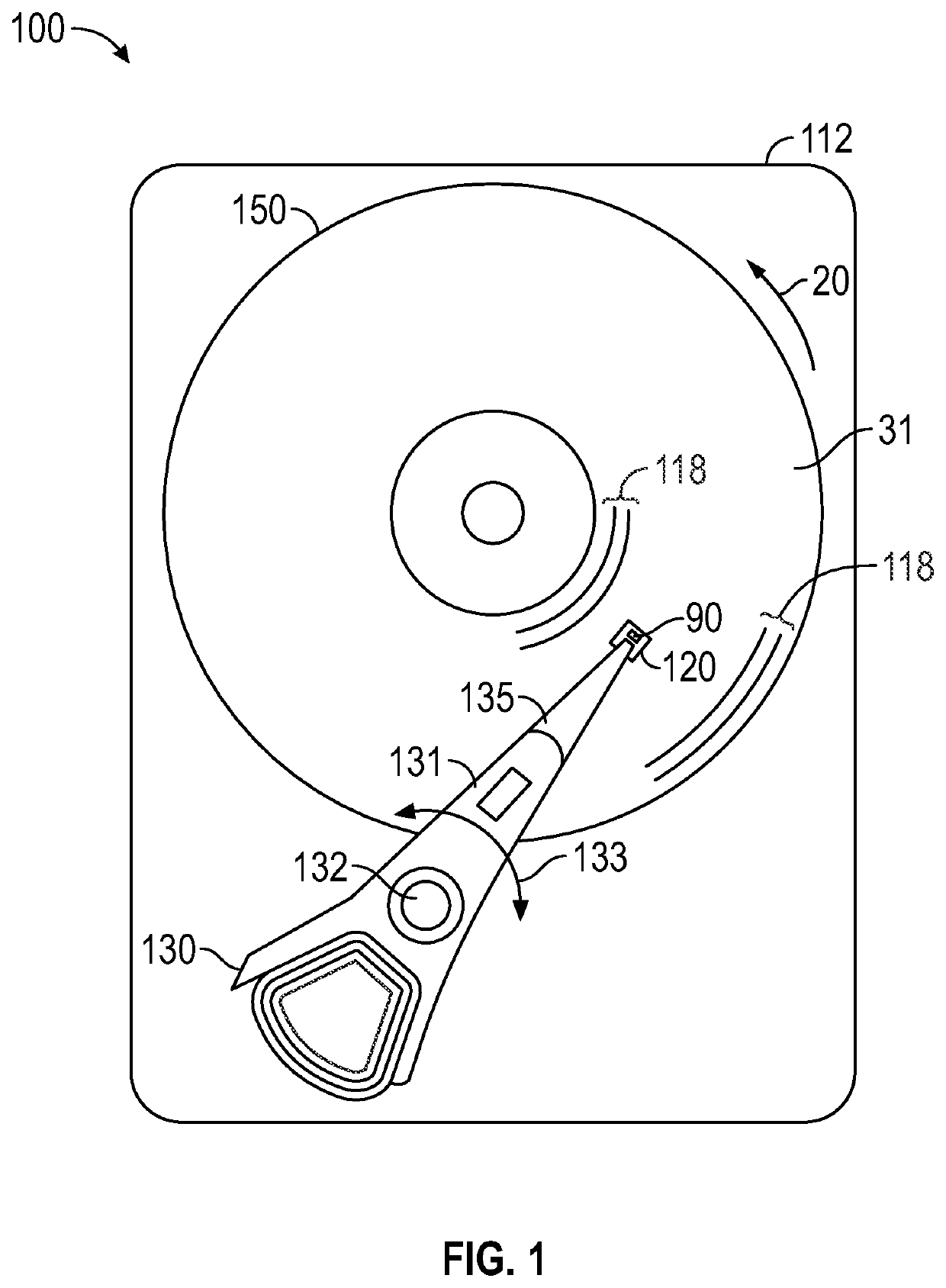
[0024]FIG. 1 is a top view of a heat-assisted recording (HAMR) disk drive 100 according to an embodiment of the invention. In FIG. 1, the HAMR disk drive 100 is depicted with a disk 150 with magnetic recording layer 31 of conventional continuous magnetic recording material arranged in radially-spaced circular tracks 118. Only a few representative tracks 118 near the inner and outer diameters of disk 150 are shown. However, instead of a conventional continuous magnetic recording layer, the recording layer may be a bit-patterned-media (BPM) layer with discrete data islands.

[0025]The drive 100 has a housing or base 112 that supports an actuator 130 and a drive motor for rotating the magnetic recording disk 150. The actuator 130 may be a voice coil motor (VCM) rotary actuator that has a rigid arm 131 and rotates about pivot 132 as shown by arrow 133. A head-suspension assembly includes a suspension 135 that has one end attached to the end of actuator arm 131 and a head carrier, such as ...


PUM

PropertyMeasurementUnit
temperatureaaaaaaaaaa
wavelengthaaaaaaaaaa
taper angleaaaaaaaaaa

Abstract

A heat-assisted magnetic recording (HAMR) head for recording data in data tracks of a HAMR disk has a gas-bearing slider that supports a near-field transducer (NFT) and a main magnetic pole formed of two layers. The first main pole layer has a cross-track width at the slider's gas-bearing surface (GBS) that tapers down in the direction towards the NFT where the optical spot is formed. The second main pole layer is located away from the NFT and has a substantially wider cross-track width than the first main pole layer so as to provide sufficient magnetic field for writing. Layers of heat sink material are located on the sloped cross-track sides of the tapered first main pole layer to reduce the temperature and thus the likelihood of oxidation of the main pole layers.

Description

CROSS-REFERENCE TO RELATED APPLICATIONS[0001]This application is a divisional of co-pending U.S. patent application Ser. No. 16 / 943,995, filed Jul. 30, 2020, which application is a divisional of U.S. patent application Ser. No. 16 / 520,250, filed Jul. 23, 2019, each of which is herein incorporated by reference.BACKGROUND OF THE DISCLOSUREField of the Disclosure[0002]This invention relates generally to a heat-assisted magnetic recording (HAMR) disk drive, in which data are written while the magnetic recording layer on the disk is at an elevated temperature, and more specifically to an improved HAMR head.Description of the Related Art[0003]In conventional magnetic recording, thermal instabilities of the stored magnetization in the recording media can cause loss of recorded data. To avoid this, media with high magneto-crystalline anisotropy (Ku) are required. However, increasing Ku also increases the coercivity of the media, which can exceed the write field capability of the write head....

Claims


Application Information

Patent Timeline
Patent Type & Authority Applications(United States)
IPC IPC(8): G11B11/105G11B11/24G11B5/21
CPCG11B11/10536G11B11/24G11B5/21G11B2005/0021G11B5/3133G11B2005/0024
Inventor MATSUMOTO, TAKUYAASIF BASHIR, MUHAMMADBALAMANE, HAMIDVAN DER HEIJDEN, PETRUS ANTONIUSSTIPE, BARRY C.
Owner WESTERN DIGITAL TECH INC
Why Eureka
Try Eureka