Corneal contact lens and method for treating myopia

Inactive Publication Date: 2000-08-15
CONTEX
View PDF2 Cites 114 Cited by
  • Summary
  • Abstract
  • Description
  • Claims
  • Application Information

AI Technical Summary

Problems solved by technology

Individuals with this condition have difficulty in focusing on distant objects because the cornea is curved too sharply to provide adequate focusing.
Myopia is a common condition for which no entirel

Method used


Image

  • Corneal contact lens and method for treating myopia
  • Corneal contact lens and method for treating myopia

Examples


Embodiment Construction

The present invention is an improvement upon my prior U.S. Pat. No. 4,952,045. The contents of my prior patent is hereby incorporated by reference.

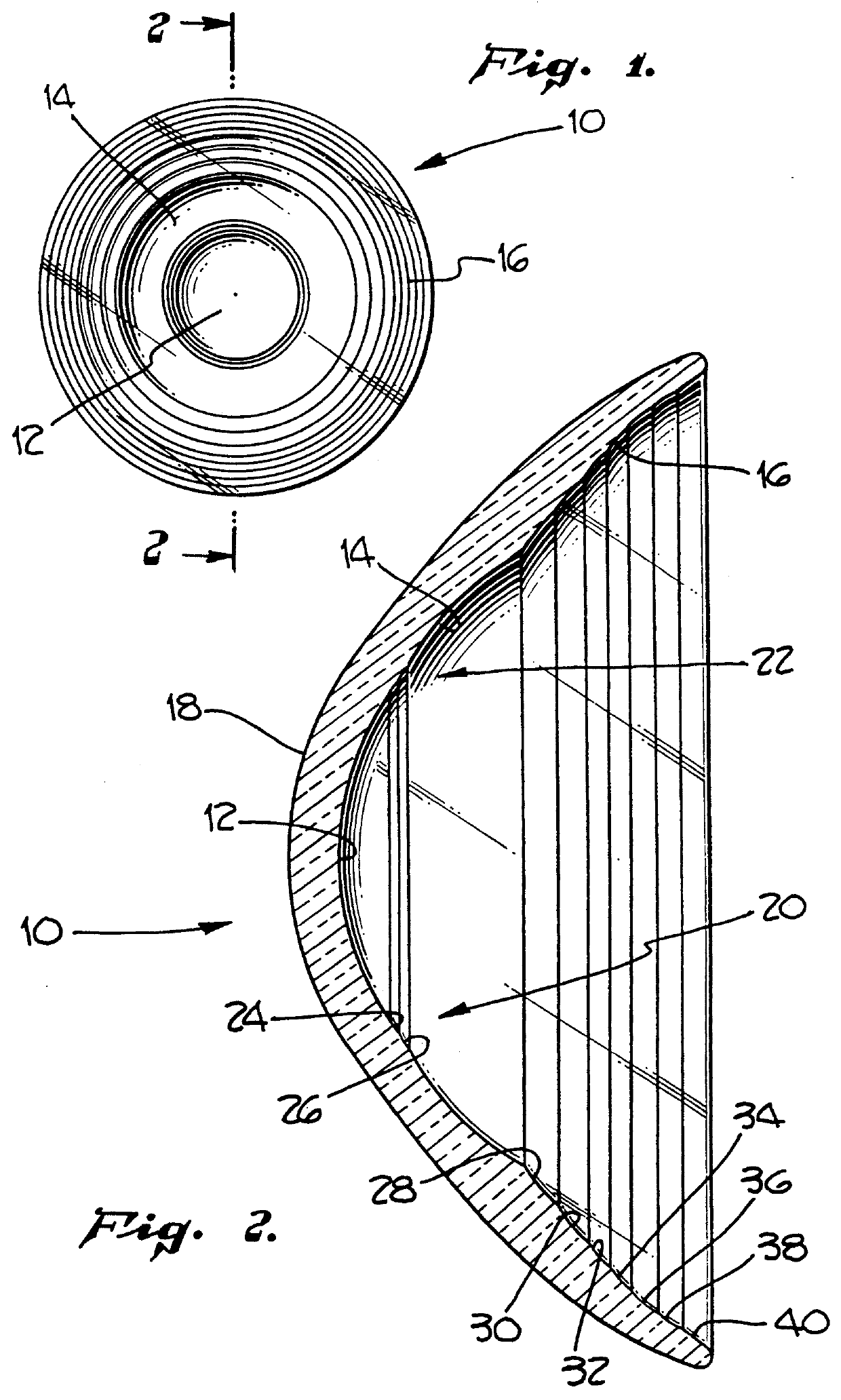
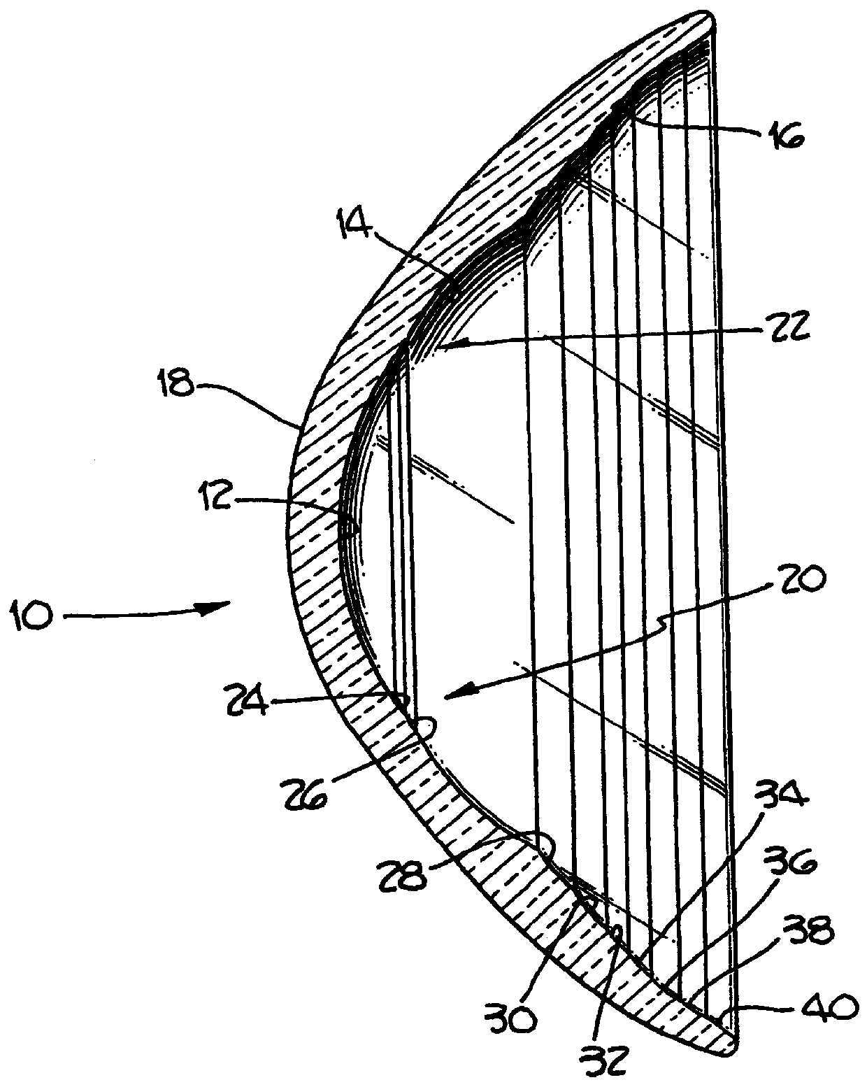
A preferred exemplary corneal contact lens in accordance with the present invention is shown generally at 10 in FIGS. 1 and 2. The lens 10 includes a central portion or zone 12, a tear portion or zone 14 and a peripheral portion or zone 16. The overall dimension of the lens 10 are within the normal ranges for corneal contact lenses. The outside diameter of the lens is typically between about 5 to 20 millimeters with other diameters being possible in special cases. The lens has a lateral or cross-sectional thickness of between about 0.05 millimeters to 10 millimeters. Thicknesses in the range of 0.05 to 0.5 millimeters are preferred.

The lens has an anterior surface 18 which is shaped in the same manner as conventional contact lenses. The posterior surface 20 is shaped to provide the central zone 12, tear zone 14 and peripheral zone 16 as w...


PUM


Abstract

A corneal contact lens for use in treating myopia by controlled corneal molding. The lens includes a central zone having a central zone radius of curvature and a tear zone. The tear zone is located concentrically around the central zone and has a radius of curvature which is smaller than the central zone. A transition zone is provided between the central zone and the tear zone wherein the transition zone has at least one transition ring. The lens may also include a peripheral zone which is located concentrically around the tear zone wherein the peripheral zone includes multiple peripheral curves having radii of curvature equal to or greater than the central zone.

Description

1. Field of the InventionThe present invention relates generally to corneal contact lenses and their use in treating myopia. More particularly, the present invention is directed to corneal contact lenses which are shaped to provide gradual altering of the patient's cornea during continued wear to reshape the cornea to reduce the myopic condition.2. Description of Related ArtMyopia, also known as nearsightedness, is a condition where the radius of curvature of the cornea is smaller than normal. Individuals with this condition have difficulty in focusing on distant objects because the cornea is curved too sharply to provide adequate focusing. Myopia is a common condition for which no entirely suitable permanent treatment has been developed.One approach to correcting myopia is through surgical reshaping of the cornea. However, such surgical procedures have not been entirely proven and there is some question as to the permanency of the surgically altered lens shape.Another approach is t...

Claims


Application Information

Patent Timeline
IPC IPC(8): G02C7/04
CPCG02C7/047G02C7/041
Inventor STOYAN, NICK
Owner CONTEX
Why Eureka
Try Eureka