Electronic-component mounting head, electronic-component mounting apparatus, and electronic-component mounting method

a technology of electronic components and mounting heads, which is applied in the direction of gripping heads, metal-working machine components, manufacturing tools, etc., can solve the problems of limited downward movement of suction devices, difficult to reduce the contact load applied by electronic components to a substrate, and difficult to reduce the contact load sufficiently

Inactive Publication Date: 2000-01-11
FUJI MASCH MFG CO LTD
View PDF23 Cites 26 Cited by
  • Summary
  • Abstract
  • Description
  • Claims
  • Application Information

AI Technical Summary

Problems solved by technology

The downward movement of the suction device is limited when the suction device abuts on a stopper provided on the head frame.
However, the prior electronic-component mounting apparatus suffer from the problem that it is difficult to reduce the contact load applied by an electronic component to a substrate.
Thus, it is difficult to sufficiently reduce the contact load (strictly, this load additionally includes the self weight of the component) and accordingly only limited sorts of electronic components can be mounted.
However, generally, the weight of a suction device is more than 4 g and accordingly this specific sort of electronic component cannot be mounted on a printed circuit board.
If a variable biasing element of a sort which has a variable-biasing-force range suitable for an electronic component of a sort which is appropriately contacted with a high contact load, is used for mounting an electronic component of a sort which is appropriately contacted with a low contact load, the electronic component of the latter sort may be contacted with an excessively large contact-load error.
On the other hand, if a variable biasing element of a sort which has a variable-biasing-force range suitable for mounting an electronic component of a sort which is appropriately contacted with a low contact load, is used for mounting an electronic component of a sort which is appropriately contacted with a high contact load, it may be difficult to provide a sufficiently large biasing force suitable for mounting the electronic component of the latter sort.
However, usually, the biasing force of at least one of the first and second biasing devices of a mounting head is different from that of another mounting head.

Method used


Image

  • Electronic-component mounting head, electronic-component mounting apparatus, and electronic-component mounting method
  • Electronic-component mounting head, electronic-component mounting apparatus, and electronic-component mounting method
  • Electronic-component mounting head, electronic-component mounting apparatus, and electronic-component mounting method

Examples


Embodiment Construction

Referring to the drawing, there will be described embodiments of the present invention in detail.

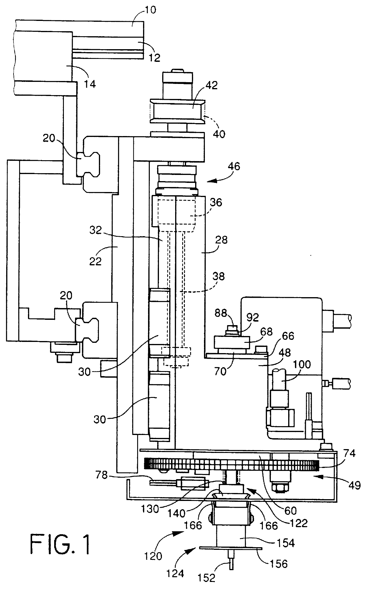
In FIG. 1, reference numeral 10 designates a frame. A guide rail 12 is fixed to the frame 10 such that the rail 12 extends parallel to x-axis directions (i.e., rightward and leftward directions in FIG. 1). An x-axis slide 14 is fit on the guide rail 12 such that the slide 14 is movable relative to the rail 12. The x-axis slide 14 is moved in the x-axis directions by an x-axis moving device, while being guided by the guide rail 12. The x-axis moving device includes a nut (not shown) fixed to the slide 14, a ball screw supported by the frame 10 such that the ball screw is rotatable relative to the frame 10 and is immovable in an axial direction thereof relative to the frame 10, and an x-axis motor 16 (FIG. 4).

A pair of guide rails 20 each of which extends parallel to y-axis directions that are perpendicular to the x-axis directions in a horizontal plane, is fixed to the x-axis slide 14. A ...


PUM

PropertyMeasurementUnit
heightaaaaaaaaaa
diameteraaaaaaaaaa
weightaaaaaaaaaa

Abstract

A mounting head, a mounting apparatus, and a mounting method which are capable of contacting an electronic component with a substrate with a small contact load and mounting the component on the substrate, are provided. A suction device 120 is fit on a splined axis portion 118 of a support shaft 84 via a ball spline 126, is biased downward by a first spring 130, and is biased upward by a second spring 134. A suction nozzle 124 is attached to a nozzle holder 122 by engaging engagement ridges 172 of sheet springs 166 fixed to the suction nozzle 124 with engagement grooves 144 of the nozzle holder 122, respectively. Prior to the mounting of electronic components 178, a relationship between contact load and position of lift 28 is obtained, and a position to which the lift 28 is moved downward for mounting each electronic component 178 is pre-determined. Thus, each component 178 is contacted with a printed circuit board with an appropriate load. Each component 178 is contacted with the circuit board with a small load, by removing the self weight of the suction device 120 owing to the biasing action of the second spring 134 and reducing the frictional resistance produced between the suction device 120 and the axis member 84 owing to the provision of the ball spline 126.

Description

1. Field of the InventionThe present invention relates to an electronic-component mounting head, an electronic-component mounting apparatus, and an electronic-component mounting method and particularly relates to the art of reducing the contact load applied by an electronic component to a substrate when the component is mounted on the substrate.2. Related ArtIn many cases, electronic components are mounted on a substrate, such as a printed circuit board, by using a suction device which applies suction to each electronic component to hold the component and which is movable upward and downward. Thus, an electronic-component mounting apparatus includes (A) a lift member which is moved upward and downward by a lifting device and (B) an electronic-component mounting head which is supported by the lift member. The electronic-component mounting head includes (a) a head frame, (b) a suction device which is supported by the head frame via a bearing such that the suction device is movable upw...

Claims


Application Information

Patent Timeline
Patent Type & Authority Patents(United States)
IPC IPC(8): H05K13/04B23P21/00B25J15/06
CPCH05K13/0408Y10T29/53178Y10S29/044Y10T29/4913Y10T29/53191Y10T29/53052H05K13/0409H05K13/0413
Inventor ASAI, KOICHIOE, KUNIOTERUI, SEIICHI
Owner FUJI MASCH MFG CO LTD
Why Eureka
Try Eureka