Adjustable wall apparatus for molding a continuous foamed plastics element

a technology of foamed plastics and molding apparatus, which is applied in the direction of dough shaping, press rollers, baking, etc., can solve the problems of poor operation flexibility of the molding apparatus of the prior art, inability to produce elements having heights, and inability to easily control the shap

Inactive Publication Date: 2000-04-04
PLASTEDIL
View PDF16 Cites 33 Cited by
  • Summary
  • Abstract
  • Description
  • Claims
  • Application Information

AI Technical Summary

Problems solved by technology

Although substantially meeting the purpose, the molding apparatus of the prior art displays poor operating flexibility and, more specifically, does not allow an easy control of the shape, and in particular of the height, of the continuous foamed plastic element where required.
It goes without saying that in addition to an undesired capital locking-up, such an `adjustment` may not in fact allow the production of elements having heights different from that predefined by the thickness of the available spacers.
This technique, furthermore, is very difficult if not impossible to apply each time it is desired to adjust the height of any lateral projections present in the continuous element, such as for example in the case of the so-called floor elements, when it is desired to impart to these elements improved thermal and acoustic insulation characteristics.
This is clearly a cumbersome and time-consuming procedure that unfavorably affects the efficiency of the molding cycle, as well as producing a not negligible waste of material.

Method used


Image

  • Adjustable wall apparatus for molding a continuous foamed plastics element
  • Adjustable wall apparatus for molding a continuous foamed plastics element
  • Adjustable wall apparatus for molding a continuous foamed plastics element

Examples


Embodiment Construction

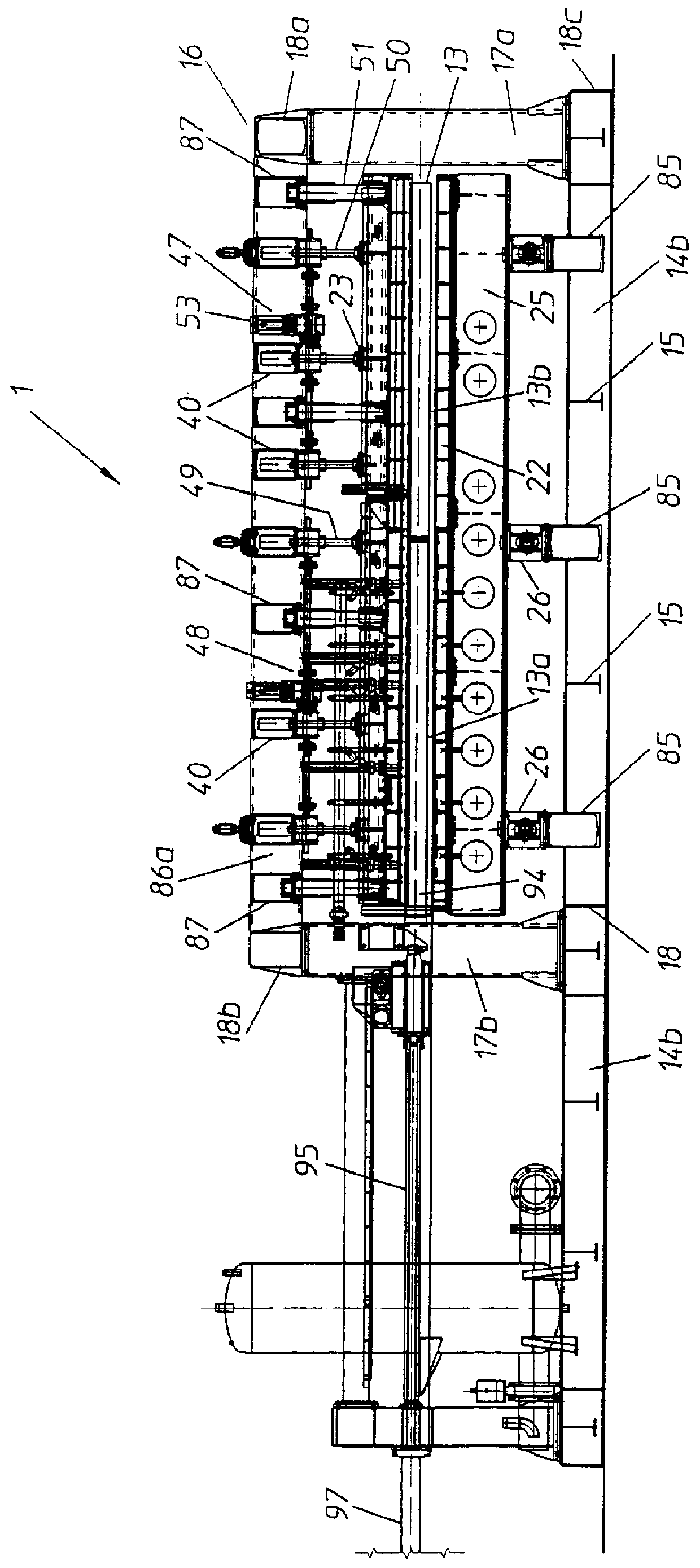
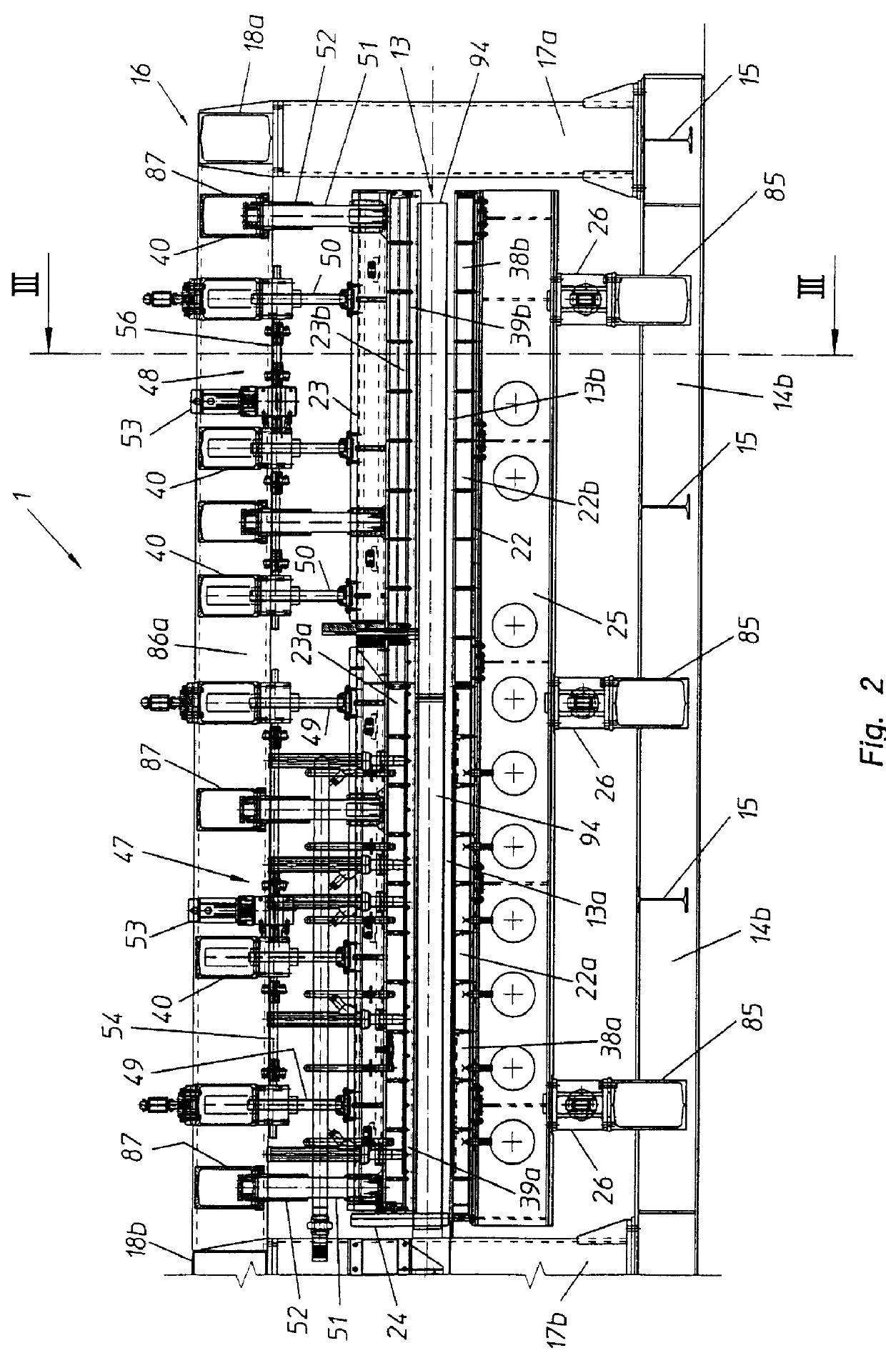
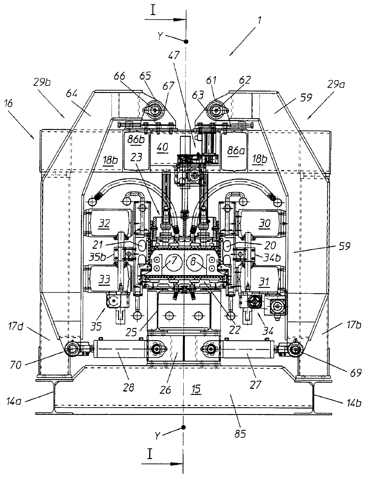
Referring to the drawing figures, generally shown at 1 is an apparatus according to the invention for molding a continuous foamed plastics element, such as a continuous element 2 for use in the construction of building floors.

In the example shown, the element 2 comprises a body 3, wherein a plurality of longitudinal parallel cavities 4 are defined, and a pair of projections 5, 6 laterally and longitudinally extending along opposite sides of the body 3. The continuous element 2 incorporates two reinforcing sectional members 7, 8, structurally identical with one another, embedded in mirror-image relationship with respect to a longitudinal plane of symmetry of the element and longitudinally extending in the central body 3 along substantially the full length of the continuous element 2.

In a preferred embodiment, the reinforcing sectional members 7, 8 are formed by suitably shaping a cold-rolled zinc-galvanized metal sheet by means of apparatuses known per se.

The reinforcing sectional me...


PUM

PropertyMeasurementUnit
heightaaaaaaaaaa
heightaaaaaaaaaa
heightaaaaaaaaaa

Abstract

An apparatus for molding a continuous foamed plastics element (2), such as a floor construction member of the type comprising a substantially parallelepipedic central body (3) and at least one lateral projection (5,6), includes a mold (13) comprising a forming chamber (13a) and a stabilization chamber (13b) defined between a bottom wall (22), a pair of opposite side walls (20,21), and a cover (23). Advantageously, the cover (23) and/or one or both the side walls (20,21) of the mold (13) comprise a plurality of structurally independent segments which may be adjustably positioned toward and away from the bottom wall (22) of the mold (13) for independently adjusting, in a substantially continuous manner, the height of the molding seats of the central body (3) and/or of the lateral projection (5,6) of the continuous element (2) in each of the forming (13a) and stabilization (13b) chambers of the mold (13).

Description

1. Field of the InventionIn a general aspect, the present invention relates to an apparatus for molding a continuous element of foamed plastics.The present invention relates, more particularly, to an apparatus for molding a continuous element of foamed plastics which finds a preferred, although not exclusive use, as a construction member in the building industry.2. Background of the InventionIn the following description and the subsequent claims, the term: "continuous foamed plastic element" is used to indicate a foamed plastic section bar, e.g. made of foamed polystyrene, which leaves the molding apparatus as a single piece substantially free from joints or breaks and having indefinite length.As is known, in the field of building construction in general, the use has long enjoyed success of foamed plastic construction elements, preferably made of foamed polystyrene, in the form of sheets or section bars of appropriate shape and size, having the function of thermal and acoustic insul...

Claims


Application Information

Patent Timeline
Patent Type & Authority Patents(United States)
IPC IPC(8): B29C44/26B29C44/00B29C44/34B29C44/58
CPCB29C44/585B29C44/26
Inventor CRETTI, PIERO
Owner PLASTEDIL
Why Eureka
Try Eureka