Cable anchor assembly

a technology of cable anchors and assembly parts, which is applied in the direction of machine supports, other domestic objects, mechanical equipment, etc., can solve the problems of increased manufacturing and installation costs, difficult manipulation, and increased tooling and assembly costs

Inactive Publication Date: 2000-04-25
AVAYA TECH CORP
View PDF12 Cites 58 Cited by
  • Summary
  • Abstract
  • Description
  • Claims
  • Application Information

AI Technical Summary

Problems solved by technology

There are, however, problems inherent in this approach.
This is problematic, especially for large diameter cables which are difficult to manipulate.
In addition, the screw assembly of the tightening element is an additiona

Method used


Image

  • Cable anchor assembly
  • Cable anchor assembly
  • Cable anchor assembly

Examples


Embodiment Construction

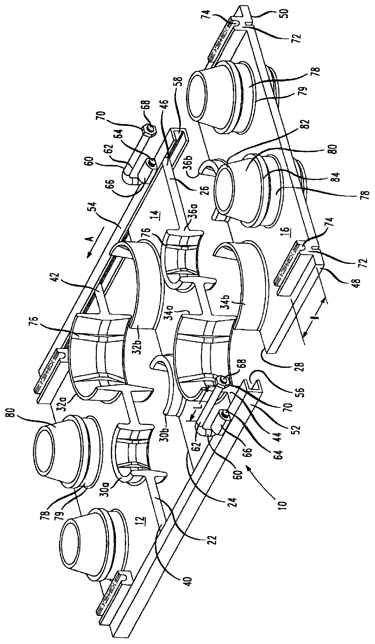
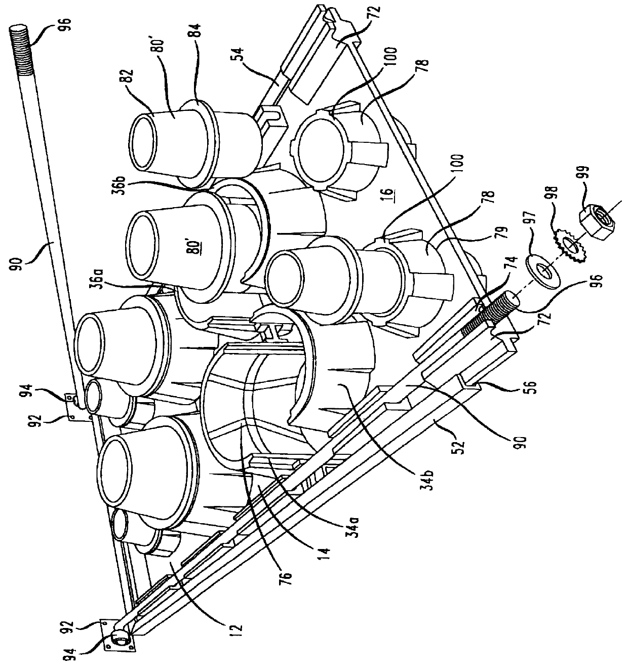
As shown in FIG. 1, a cable anchor assembly 10 in accordance with a preferred embodiment of the present invention includes a plurality of plates 12, 14 and 16. The plates are arranged, as shown, so that two of the plates (12 and 16) comprise end plates which abut and enclose a center plate (plate 14). Each plate has at least one engaging edge that engages an opposing engaging edge of an adjacent plate. For example, and as explained more fully below, plate 12 has an engaging edge 22 which is brought into contact with an engaging edge 24 of plate 14. Edge 28 of plate 16 is brought into contact with a second engaging edge 26 of plate 14. The plates may be constructed by molding them from any substantially rigid material, such for example as plastic, metal, etc. although, due to its weather durability, plastic is preferred.

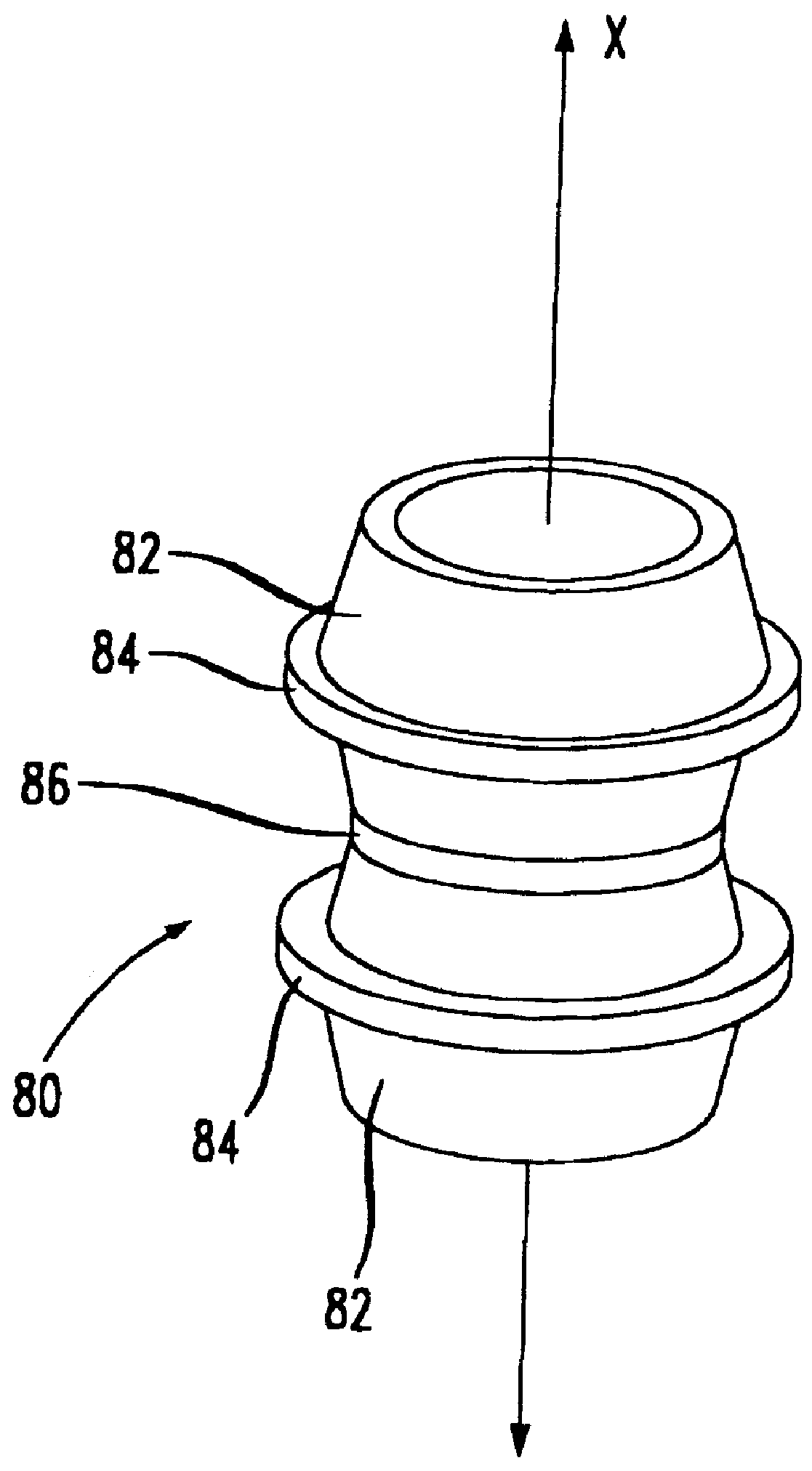
Each engaging edge forms a portion of a formable collar for seating about a sleeve or a cable, and for accommodating cable passage through assembly 10 when the plates...


PUM


Abstract

A cable anchor assembly for facilitating ready anchored connection of cables to components while protecting the cables from external forces and from moisture. The assembly includes a plurality of plates slidably engageable along a rail for facilitating relative movement between the plates. Each plate has an engaging edge that defines a portion of a formable collar in which a cable is receivable. A fixture, such as a rubber boot, is placed over a section of the cable and, with the plates separated, the cable section is placed between the formable collar portions, whereupon the plates are brought into sliding edge-to-edge contact with each other to enclose the cable section and boot. With the plates in contact, a securing mechanism is operated to maintain contact between the plates. In a preferred embodiment, the boot is configured to create a substantially water-resistant seal between the cable section and the movable plates.

Description

I. Field of the InventionThe present invention relates to cable anchors and, more particularly to a cable anchor assembly for installing cables in electrical cabinets and enclosures typically located outdoors.II. Description of Related ArtCable anchors and rubber boots are generally well known in the art and are used to install cables and to lead cables through walls, cabinets, enclosures and like structures. One example of such a device is found in U.S. Pat. No. 4,767,086 (Blomqvist) which discloses a tightening device for a cable bushing arrangement. The device includes a rigid frame structure having packing pieces arranged in rows with the packing pieces having cable accommodating holes. A tightening device which includes a pressure plate is located between the frame structure and the adjacent rows of packing pieces, and a tightening element, such as a screw, is situated between the frame structure and the pressure plate to force the pressure plate against the rows of packing pie...

Claims


Application Information

Patent Timeline
IPC IPC(8): F16L5/10F16L5/02
CPCH02G3/22F16L5/10F16L5/14
Inventor DISPENZA, JOHN ANTHONY
Owner AVAYA TECH CORP
Why Eureka
Try Eureka