Steam generator

a generator and steam technology, applied in the field of steam generators, can solve the problems of user frustration and significant length of tim

Inactive Publication Date: 2000-06-06
IRENCO
View PDF21 Cites 15 Cited by
  • Summary
  • Abstract
  • Description
  • Claims
  • Application Information

AI Technical Summary

Benefits of technology

FIG. 3 is a schematic circuit diagram of an electronic control circuit of the steam generator; and
FIG.

Problems solved by technology

Known steamers tend to require a significant length of time to boil s

Method used


Image

  • Steam generator
  • Steam generator
  • Steam generator

Examples


Embodiment Construction

The illustrated steam generator was designed to form part of a wall mounted steamer with a flexible hose for use in steaming clothes. However, it will be appreciated that the steam generator of the invention could be used in numerous other applications.

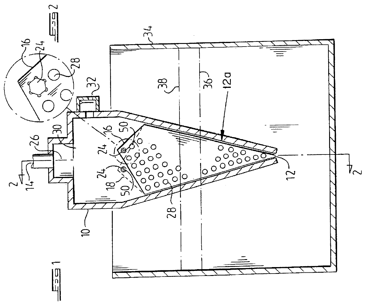
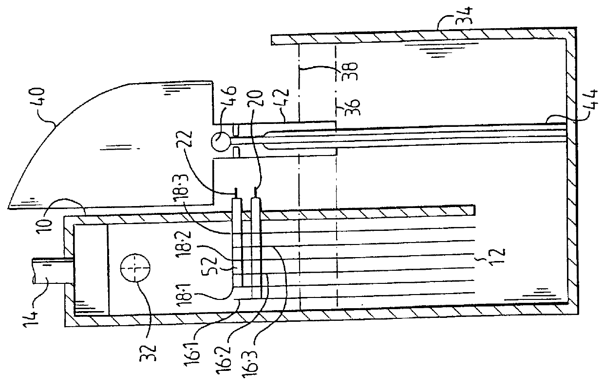
Referring now to the drawings, the illustrated steam generator comprises a steam chamber 10 which has a choked inlet 12 at its lowermost end and a steam outlet 14 at its uppermost end to which will normally be connected a flexible tube or pipe to convey steam to a point of application. The steam chamber is constructed from a heat resistant, non-conductive material such as mineral filled polypropylene. As can best be seen in FIG. 1, the steam chamber tapers towards the inlet 12 to define a tapered zone 12a.

Within the steam chamber 10, in the tapered portion thereof, are two sets of metallic plates 16 which are interleaved as best seen in FIG. 2 and which function as the electrodes of the steam generator. Three plates 16.1, 16.2 and 16....


PUM


Abstract

A steam generator comprises a chamber having an inlet for water and an outlet for steam. Disposed in the chamber are first and second sets of interleaved electrodes, connected to respective poles of an electrical supply. The electrodes have tapered planar surfaces extending adjacent one another, with a cross sectional area which increases in a direction away from the inlet for water. The electrodes also have multiple apertures formed in the planar surfaces. The chamber is tapered complementally to the shape of the electrodes, and is mounted within a primary reservoir. The inlet for water is in liquid communication with the interior of the primary reservoir and the level of the liquid in the primary reservoir is maintained constant.

Description

BACKGROUND TO THE INVENTIONThis invention relates to a steam generator.Steam generators comprising a pair of electrodes which are immersed in water are known for various applications. For example, humidifiers are known which operate on this principle, as well as steamers which can be used to remove creases from clothing.Known steamers tend to require a significant length of time to boil sufficient water to create steam, which can be frustrating for a user.It is an object of the invention to provide a steam generator which operates relatively rapidly.According to the invention a steam generator comprises a chamber having an inlet for water, an outlet for steam, and at least two electrodes disposed side by side in the chamber, at least two adjacent electrodes having planar surfaces extending adjacent one another, with a plurality of apertures being formed in the planar surfaces.Preferably a plurality of first electrodes are interleaved with a plurality of second electrodes, the first ...

Claims


Application Information

Patent Timeline
IPC IPC(8): F22B1/30F22B1/00
CPCF22B1/30
Inventor BENADE, LUDWICK JACOBUSBLOMERUS, ZACHARIAS
Owner IRENCO
Why Eureka
Try Eureka