Framing member

a framing member and joining technology, applied in the direction of girders, dismountable cabinets, building repairs, etc., can solve the problems of increased cost, difficult to obtain such members at a reasonable price, and much more labor or tools

Inactive Publication Date: 2000-07-18
ADO SUPESU
View PDF5 Cites 36 Cited by
  • Summary
  • Abstract
  • Description
  • Claims
  • Application Information

AI Technical Summary

Problems solved by technology

So far, as framing wooden members in, for example, housing and other structures, what is called "solid shafts" cut out from lumber have been generally available, but recently as much more attention has been paid for the saving of natural resources and overhead costs have increased, it has been very difficult to obtain such members at a reasonable price.
With the framing members according to the prior art, however, until the connection portions are

Method used


Image

  • Framing member
  • Framing member
  • Framing member

Examples


Embodiment Construction

Now, description will be made for embodiments according to the present invention, referring to foregoing drawings:

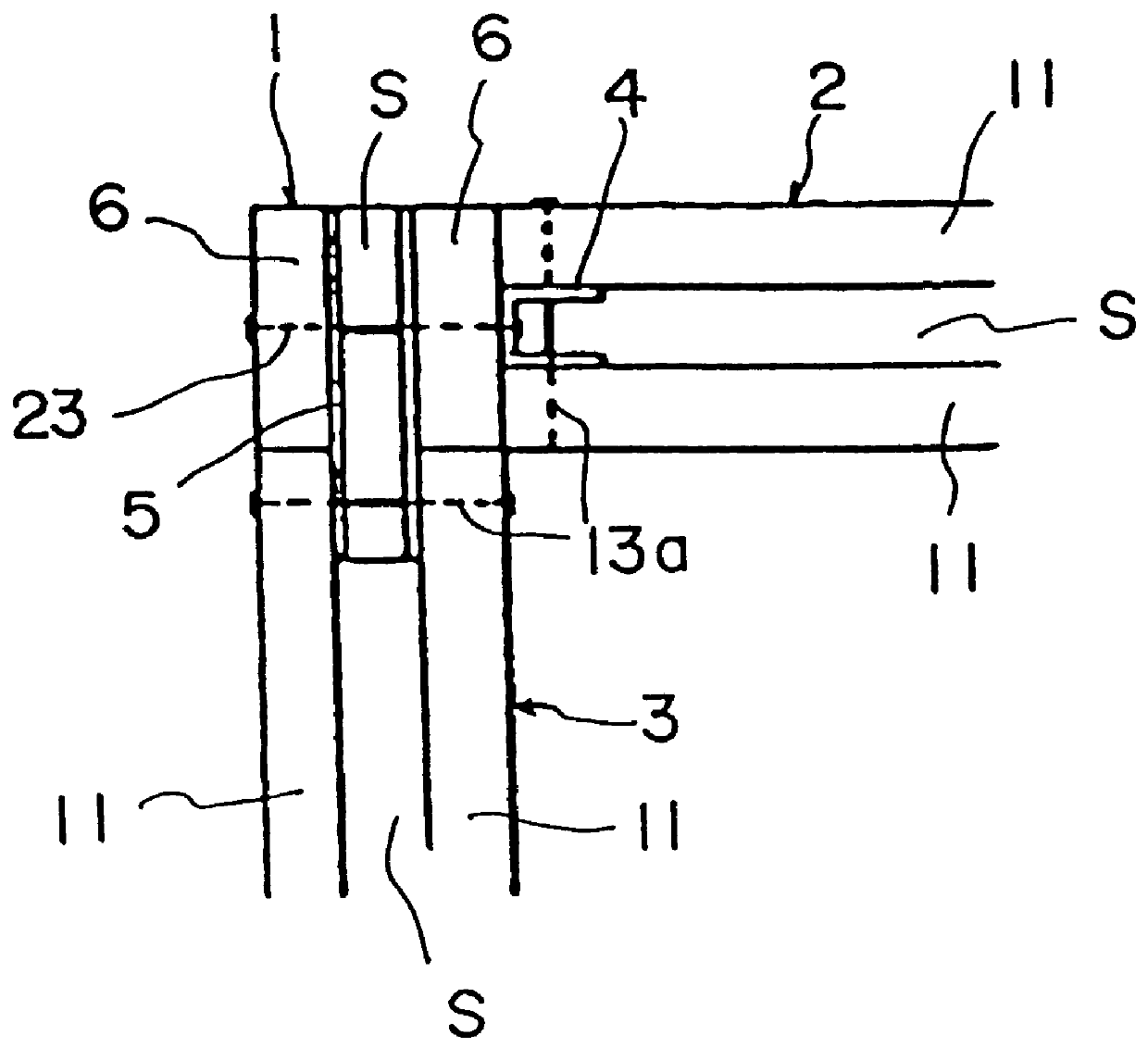
FIG. 1 is an illustration showing a joint structure jointed by the jointing method of the framing members according to the present invention; In the drawing, Numeral 1 is a framing column; 2 is a front-side (framing) horizontal member; 3 is an end-side (framing) horizontal member; 4 is a front-side (side-surface) joint fixture; and 5 is an end-side (opening) joint fixture.

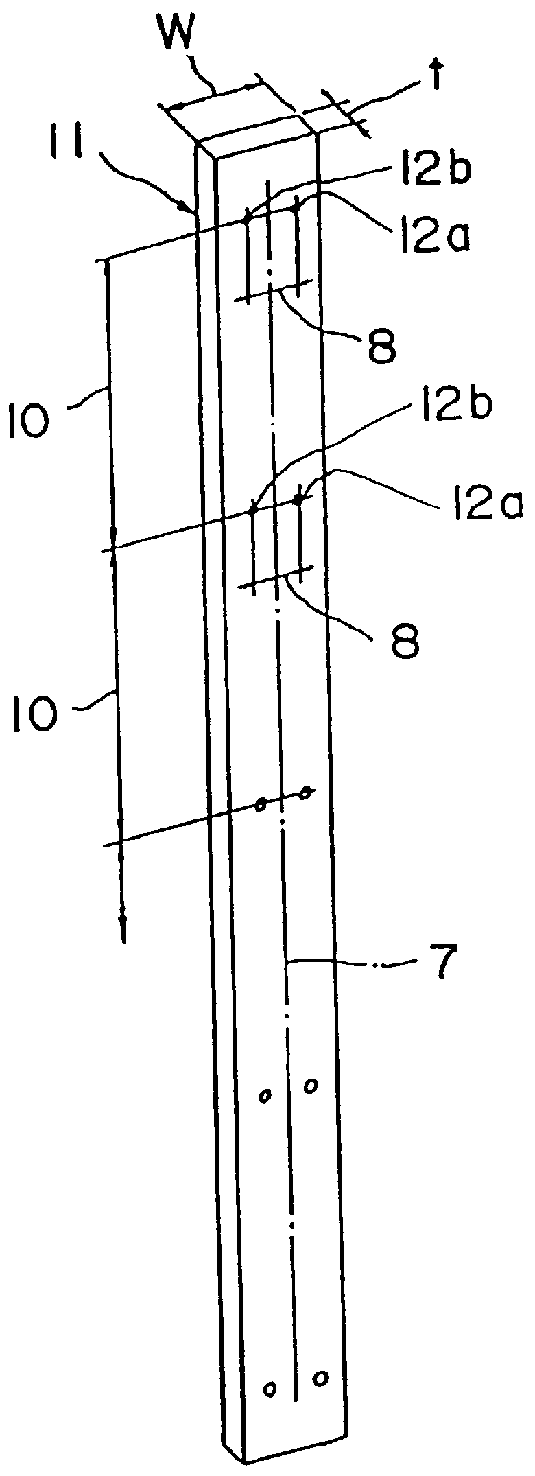
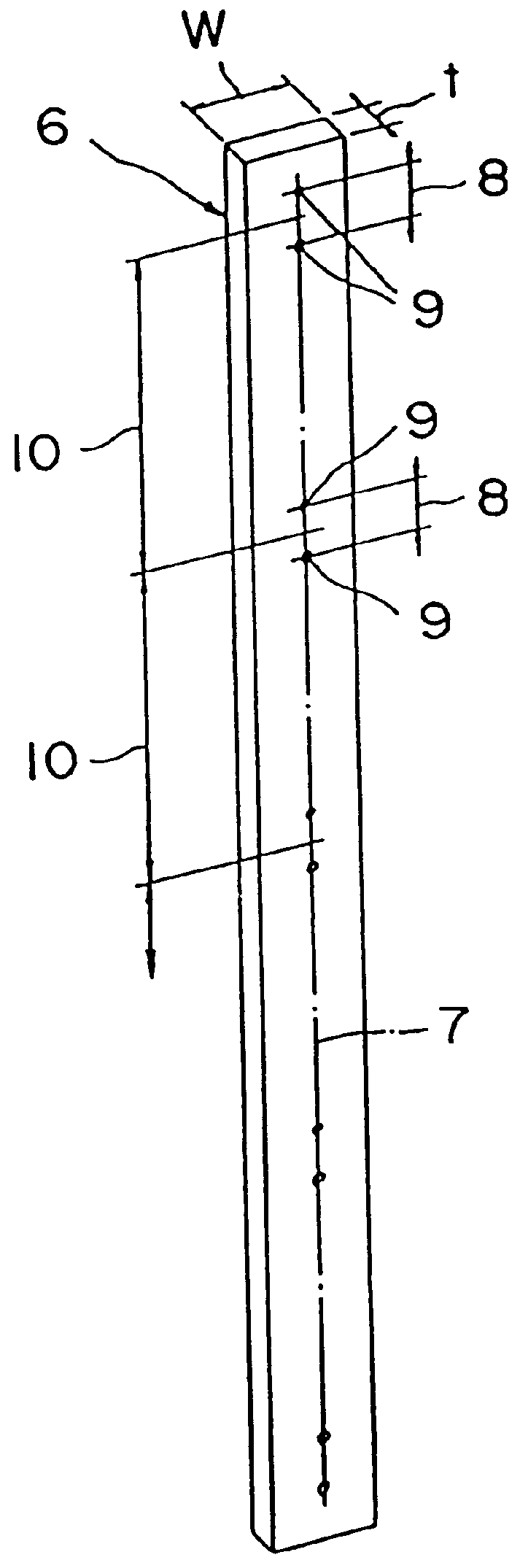
The framing column 1 is a composite substructure of a pair of long-size slender members 6 facing each other. The width w of the slender member 6 is three times the thickness t. The framing member 1 is formed by providing an opening s (s=t) in between the slender members 6, 6. In the lateral (or wider) surfaces of the column 1 (including the top end), a plurality of pairs of through holes 9, 9 for fixing the joint fixtures (fixture fixing through holes 9, 9) with a small pitch or spacing 8 (1 / 2 w long) a...


PUM

PropertyMeasurementUnit
Lengthaaaaaaaaaa
Shapeaaaaaaaaaa
Dimensionaaaaaaaaaa

Abstract

PCT No. PCT/JP96/03640 Sec. 371 Date Sep. 25, 1998 Sec. 102(e) Date Sep. 25, 1998 PCT Filed Dec. 12, 1996 PCT Pub. No. WO97/22766 PCT Pub. Date Jun. 26, 1997A frame material that can be easily formed as a pillar or beam by appropriately adjusting the length and/or strength thereof, a joint portion of which is uniform and smooth, a residual portion of which can be used as a joint, and which can easily be combined with other building materials. The frame material is formed into an elongate shape, and a cross section crossing at right angles a longitudinal axis thereof is formed into a rectangular shape with the length of a shorter side of the rectangular cross section being made one-third of the length of a longer side. The frame material comprises in combination a frame material in which a pair of through holes (5,5) are provided at a predetermined pitch on a center line (4) of a front side whose lateral width (w) is constituted by the longer side of the cross section, the hole pitch of the pair of through holes being a half of the lateral width, and a frame material in which a pair of through holes (5, 5) are provided on a line crossing at right angles the center lines at a hole pitch of a half of the lateral width in such a manner as to be symmetric with respect to the center line, and pairs of through holes are provided along the center line (4) at the predetermined pitch. In this case, the pitch of the through holes (5, 5) on the center line may be provided so as to be equal to a module dimension of a building material.

Description

TECHNOLOGICAL FIELDThis invention relates to a jointing method of framing members mainly suitable for constructing housing and other structures.TECHNOLOGICAL BACKGROUNDSo far, as framing wooden members in, for example, housing and other structures, what is called "solid shafts" cut out from lumber have been generally available, but recently as much more attention has been paid for the saving of natural resources and overhead costs have increased, it has been very difficult to obtain such members at a reasonable price. Therefore, a various shape of members have been proposed for the market. One of them is formed by solidly securing a plurality of wooden plates facing each other at a certain interval of spacing.Framing members with such conventional construction are formed by solidly binding both members by adhesives or bolting after the end portion of one framing member is inserted into an opening in the other member.With the framing members according to the prior art, however, until...

Claims


Application Information

Patent Timeline
IPC IPC(8): A47B47/00A47B47/04A47B96/14A47B96/00E04B1/26E04C3/42E04C3/38F16B12/00F16B12/46B27M3/00E04B1/58E04C3/12E04C3/36
CPCA47B47/04A47B96/145E04B1/26E04C3/38E04C3/42F16B12/46E04B1/2604
Inventor MATSU, YOSHITAKAMARUYAMA, SHIGEHISASHIBATA, TETSUFUMI
Owner ADO SUPESU
Why Eureka
Try Eureka