Apparatus and method for pre-capping containers

Inactive Publication Date: 2000-09-12
NEW ENGLAND MACHINERY
View PDF17 Cites 42 Cited by
  • Summary
  • Abstract
  • Description
  • Claims
  • Application Information

AI Technical Summary

Problems solved by technology

Frequently, caps do not settle squarely on the container opening so that when the caps are tightened they remain out of alignment and fail to seal to the container properly.
Such force frequently damages the thread of threaded containers or the mouths of the containers resulting in caps having a failed seal.
Such failed seals

Method used


Image

  • Apparatus and method for pre-capping containers
  • Apparatus and method for pre-capping containers
  • Apparatus and method for pre-capping containers

Examples


Embodiment Construction

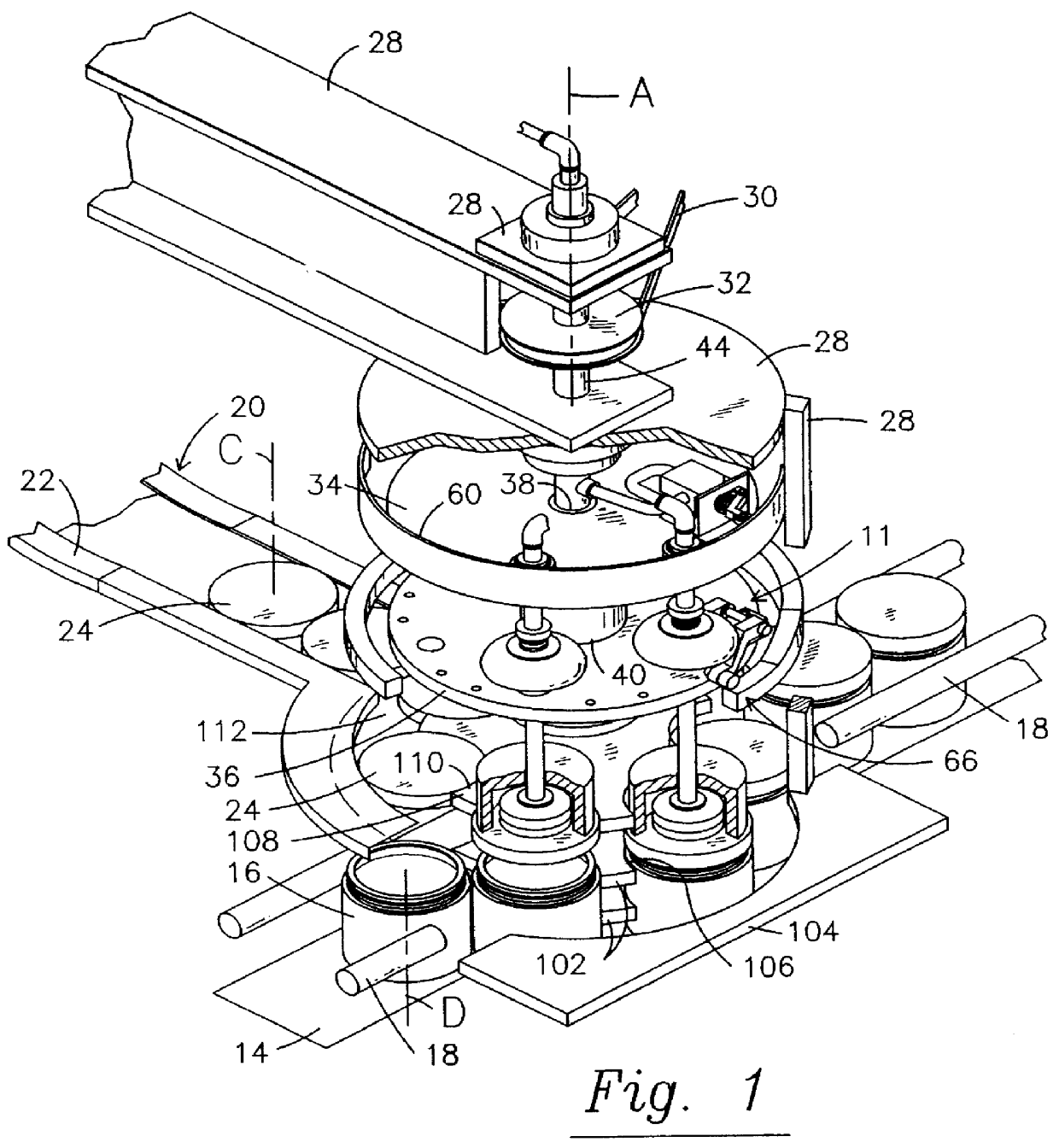
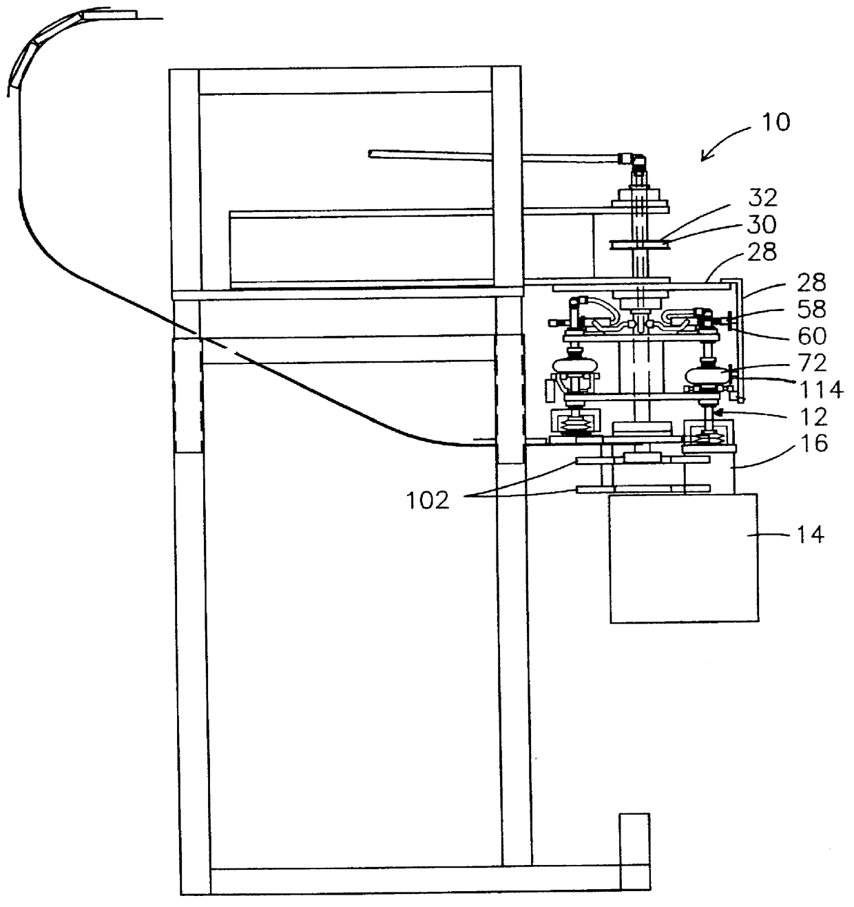
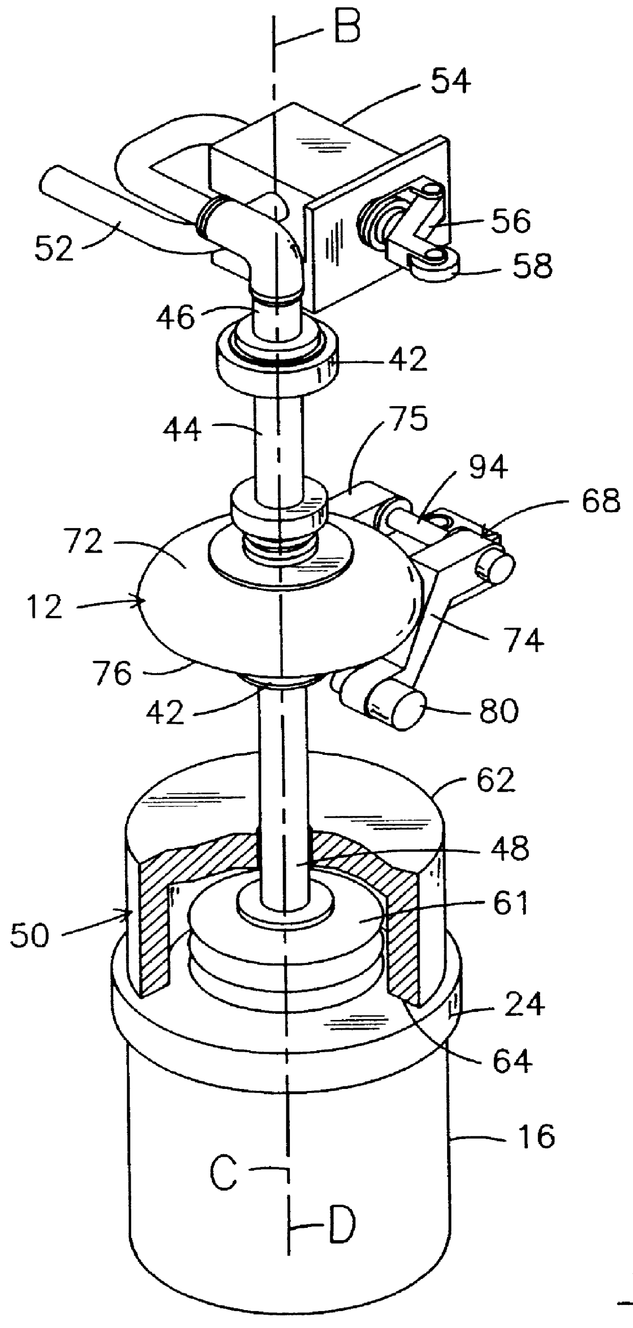
A preferred embodiment of the apparatus and the method of this invention is illustrated in FIGS. 1-8, and such apparatus is used in working relationship with other, related devices that may include, for example, a conventional capping machine. In this application, a cap is defined to include threaded caps, overcaps, plugs, and other fitments. The precapping apparatus 10 comprises a turret assembly 11 that has at least one spindle assembly 12, but in the embodiment illustrated in the Figures, six spindle assemblies 12 have been shown, as it is an efficient configuration. The apparatus, 10 further comprises a conveyor 14 that moves containers 16 to the turret assembly 11 between two guide rails 18 and a cap delivery system 20, which is well known in the art. The cap delivery system 20 has a chute 22 that delivers caps 24 to the turret assembly 11.

The turret assembly 11 comprises a column 26 and an apparatus axis that conveniently lies along the vertical axis A of column 26. The column...


PUM


Abstract

An improved pre-capping machine and method for pre-capping containers that are advanced along a predetermined path by standard conveyor systems. The present invention pretightens caps, plugs, overcaps and other fitments to ensure that they are squarely placed on the containers, without damage to the containers, in preparation for their final closure. The apparatus comprises a spindle assembly, having a longitudinal spindle axis, that is connected to a frame for movement of the spindle assembly along the spindle axis. The spindle assembly comprises a cap gripper that is configured to hold a cap centered over the open end of a container so that axes through the cap, the open end of the container and the spindle assembly generally coincide. To place a cap on the container, the spindle is released for free movement along the spindle axis.

Description

1. Field of the InventionThe present invention relates to an apparatus for placement of caps, plugs, overcaps and other fitments into contact with their containers. The apparatus will pretighten the caps, plugs, overcaps and other fitments to ensure that they are squarely placed on the containers in preparation for their final closure.2. Description of the Prior ArtBottle capping machines have been in existence for over twenty years. On most capping machines, the system for placing caps on containers prior to tightening comprises a chute that delivers caps into the path of the containers that are being fed into the capping machine. The cap is held at an angle so that the leading edge of the cap engages the open end of the containers stripping the cap from the delivery chute so that the caps rest on the open end of the container. The containers advance to a tightening station that rotates threaded caps to a predetermined torque or presses other fitments downwardly into the container ...

Claims


Application Information

Patent Timeline
IPC IPC(8): B65B7/28
CPCB65B7/28B65B7/2835
Inventor BANKUTY, GEZA E.PERAZZO, NICHOLAS J.
Owner NEW ENGLAND MACHINERY
Why Eureka
Try Eureka