Dampenable bearing

a bearing and a technology of adamant bearings, applied in the direction of bearing unit rigid support, shock absorption, shock proofing, etc., can solve the problems of limiting the movement ability of ball bearings, dampening the movement ability of objects or work pieces attached to mounting plates in relation to the base,

Inactive Publication Date: 2000-09-12
BROTZ GREGORY R
View PDF8 Cites 57 Cited by
  • Summary
  • Abstract
  • Description
  • Claims
  • Application Information

AI Technical Summary

Problems solved by technology

If a magneto rheological fluid is used, a magnetic field can be applied to such magneto rheological fluid to stiffen it which process also limits the a

Method used


Image

  • Dampenable bearing
  • Dampenable bearing
  • Dampenable bearing

Examples


Embodiment Construction

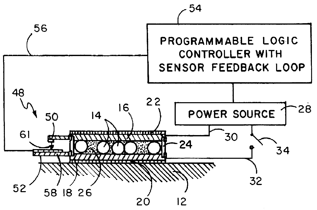
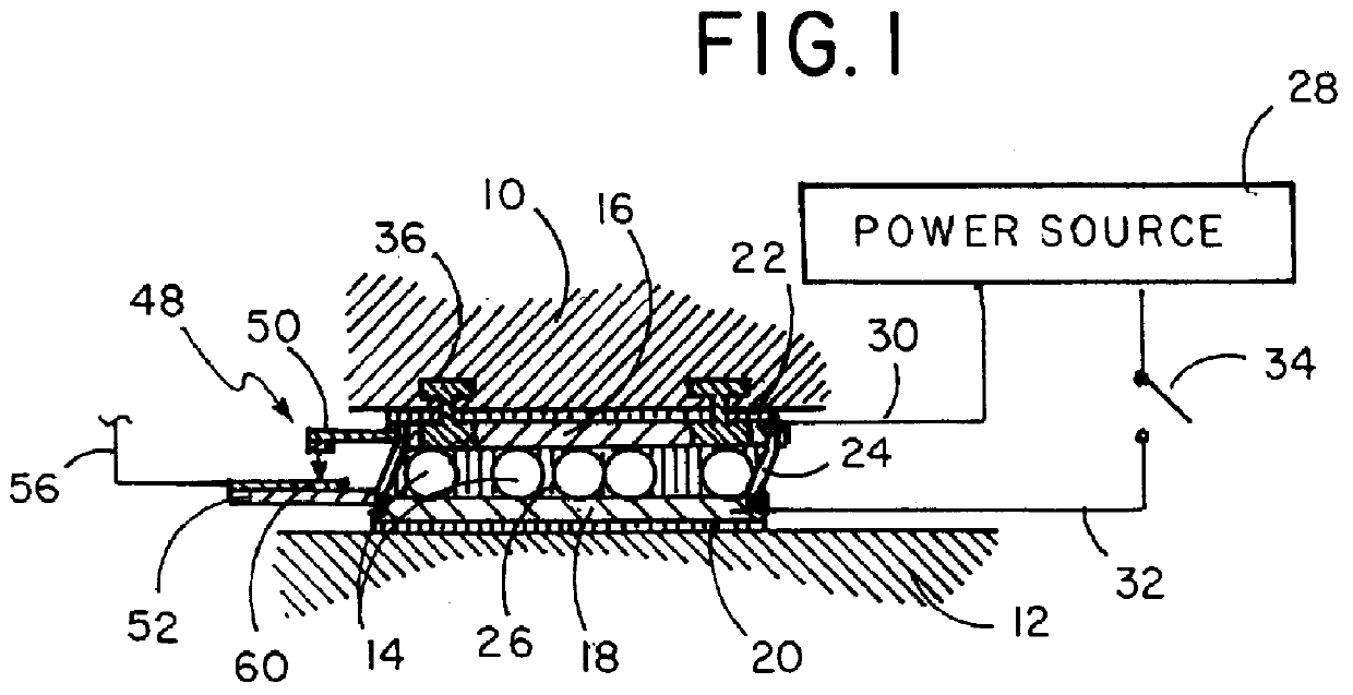
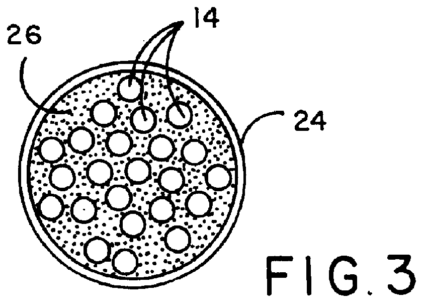
FIG. 1 illustrates a side view of the device of this invention wherein mounting plate 22 is disposed above base 12. Separating mounting plate 22 from base 12 is a plurality of ball bearings 14. Between object 10 mounted on mounting plate 22, as seen in FIG. 2, and the tops of ball bearings 14 is upper electrode plate 16, and between the bottoms of the ball bearings 14 and base 12 is lower electrode plate 18. Lower electrode plate 18 is affixed to base plate 20. Surrounding the upper electrode plate / ball bearings / lower electrode plate sandwich is a retaining member such as elastic ring 24 which contains and holds the electro rheological fluid or magneto rheological fluid 26 therein around ball bearings 14. Although a plurality of ball bearings is seen in this cross-sectional view, it should be noted that more or less ball bearings can be utilized depending upon the structure of the object being supported. When utilizing electro rheological fluids, in most cases it is desirable that t...


PUM


Abstract

A dampening bearing support member having a plurality of bearings disposed between an object and a base with rheological fluid disposed around the bearings and structure to retain the rheological fluid in such position, with the rheological fluid being under the control of the user at times when it is desired to stiffen the rheological fluid and limit or prevent movement of the bearings and the object in relation to the base.

Description

1. Field of the InventionThe device of this invention is a dampenable bearing that is adjustable, such bearing in a first mode having the ability to move laterally and in a second mode being fixed in position and more particularly relates to a bearing structure having a plurality of ball bearings disposed between two electrode plates with an electro or magneto rheological fluid disposed between such plates and ball bearings, which device, upon activation and resulting stiffening or solidification of such rheological fluid, slows down movement and can dampen movement to the point of preventing movement of such bearings, thereby fixing the positioning of such plates in relation to one another.2. Description of the Prior ArtThere are some situations when a work piece, machine or other object requires adjustable movement dampening from a point of allowing movement to a point of preventing movement. Movement dampening in the prior art can be accomplished by having wheels on an object whi...

Claims


Application Information

Patent Timeline
IPC IPC(8): F16C23/00F16C27/00F16F9/53
CPCF16C23/00F16C27/00F16F9/53F16F2230/14F16C2210/04
Inventor BROTZ, GREGORY R.
Owner BROTZ GREGORY R
Why Eureka
Try Eureka