Switch with a rocker, which has an affixed magnet

a technology of rocker and switch, which is applied in the direction of waveguide type devices, relays, dynamo-electric relays, etc., can solve the problems of plastic deformation of inability to reliably contact the connector, and inability to properly contact the contact portion of the plate spring

Inactive Publication Date: 2000-09-26
K M W CO LTD
View PDF1 Cites 29 Cited by
  • Summary
  • Abstract
  • Description
  • Claims
  • Application Information

AI Technical Summary

Problems solved by technology

When the stress is persistent, there is a problem that fatigue happens in the area @.
Furthermore, the contacted portion of the plate spring can be plastic-deformed while the plate spring is pushing one of the dielectric pins for a long time.
In this case, the connectors cannot be properly contacted reliably by the reed because the pressure provided by the dielectric pin can be weakened due to the plastic deformation of the plate spring.

Method used


Image

  • Switch with a rocker, which has an affixed magnet
  • Switch with a rocker, which has an affixed magnet
  • Switch with a rocker, which has an affixed magnet

Examples


first embodiment

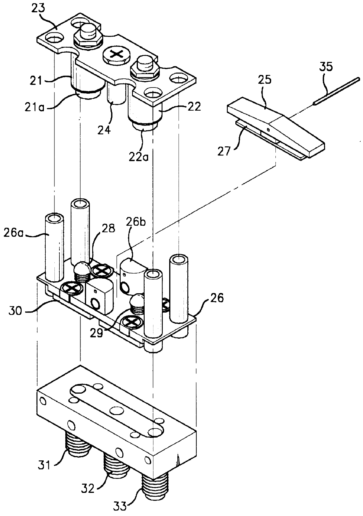
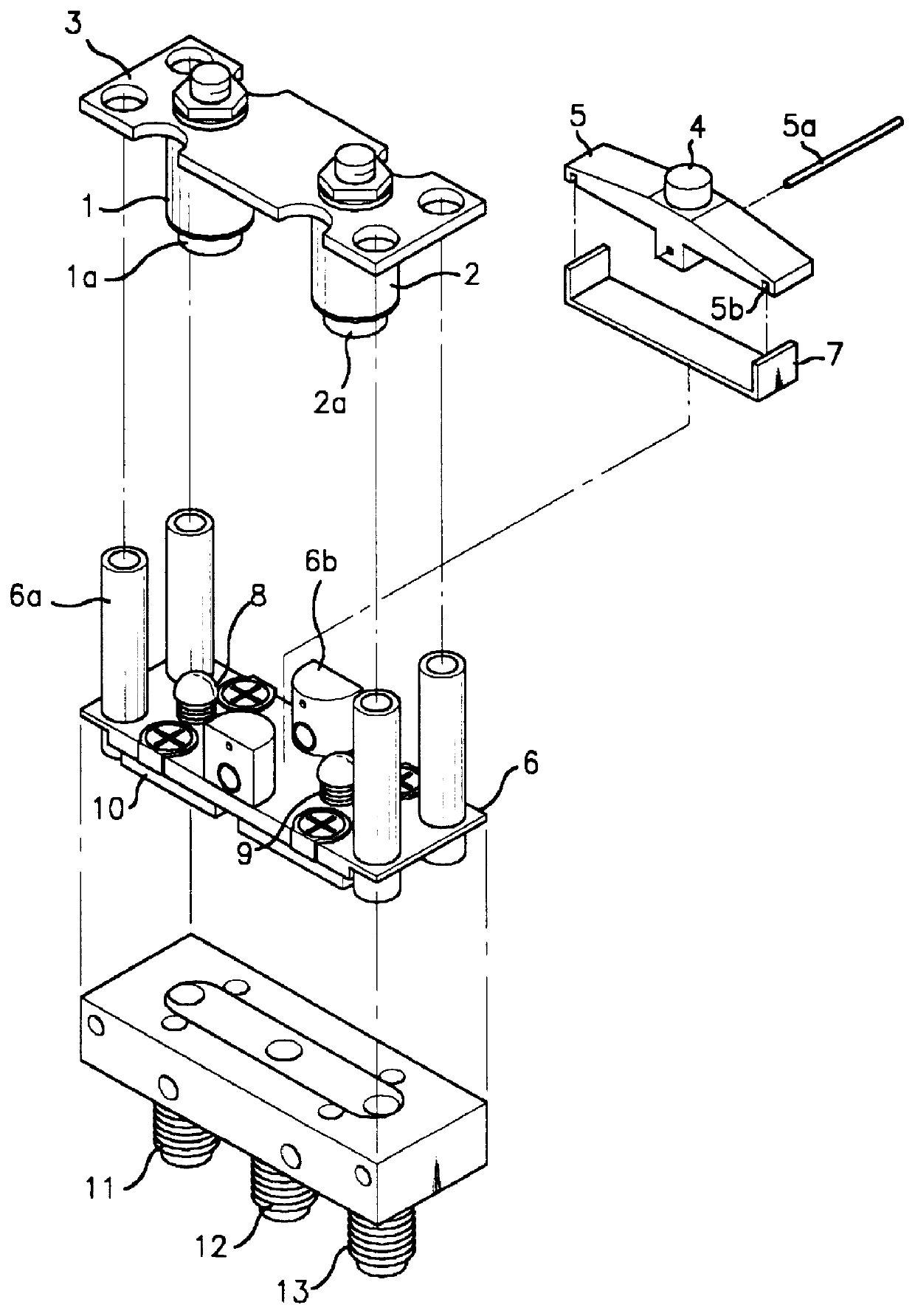
As shown in FIG. 3, the switch of first embodiment according to the present invention has a supporting plate 3, with a through hole in each corner thereof. A base-cover 6 is located under the supporting plate 3. Three connectors 11 to 13 are located under the base-cover 6. The present invention also has a rocker 5, which is made of a metal that can be magnetized and disposed on the base-cover 6. In this case, the rocker 5 has a permanently affixed magnet 4 on the upper and center surface thereof and the rocker 5 is magnetized by the attached magnet 4.

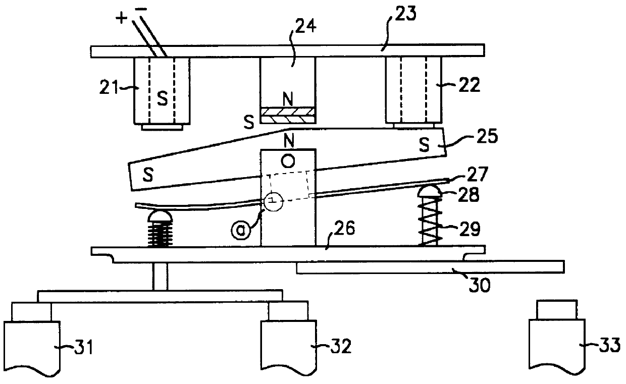
The supporting plate 3 has a first and second solenoids 1 and 2 respectively disposed on both ends of bottom surface thereof. The solenoids 1 and 2 have bobbin cores 1a and 2a respectively therein, so that the solenoids 1 and 2 can function as an electromagnet when a power is supplied. In this embodiment, when a power is supplied to one of the solenoids, the solenoid has an S pole (South Pole) on the lower portion thereof, in accordance...

second embodiment

As shown in FIG. 7, the switch comprises of a post 14 disposed between the two solenoids 1 and 2. In this case, when power is supplied to the switch of this embodiment and the rocker 5 is inclined, the post 14 is changed to an electromagnet having an S pole on the lower portion thereof. Therefore, when the rocker 5 is seesawed, the inclined state of the rocker 5 is retained by a resultant force of the attraction occurred between the solenoid 1 or 2 and the permanent magnet 4 and the attraction occurred between the post 14 and the permanent magnet 4.

As the above-mentioned the first and the second embodiments, this invention is not limited to the structure which the rocker 5 is magnetized by the permanent magnet 4 disposed on the upper surface thereof. Therefore, as shown in FIG. 8, in the third embodiment of the present invention, the rocker 5 has two permanent magnets 4 disposed on both end portions of the upper surface thereof in order to be contacted with the each solenoid dispose...


PUM


Abstract

The present invention relates to a switch with a rocker, which has an affixed magnet, capable of being reliably opened or closed by a mechanical operation of a magnetized rocker. The present invention comprises of a supporting plate and a plurality of electromagnets occurring a magnetic force when a power is supplied thereto and being disposed in a bottom surface of the supporting plate. Further, the present invention has a rocker made of a magnetic substance, magnetized in order to occur repulsion with the electromagnet and then rotated by a predetermined angle. Furthermore, the present invention at least one magnet for magnetizing the rocker and retaining an inclined state of the rocker by the if occurred attraction with the electromagnet, and being disposed on the rocker. Also, the present invention has a plate spring, to provide a pressure along with the rotation of the rocker, having erect portions on both end portions thereof, in which the erect portions are fixed to the rocker, and a contact means to contact with connectors by the pressure of the plate spring.

Description

1. Field of the InventionThe present invention relates to a switch with a magnetized rocker utilized in a part of a super-high frequency system such as an N-way power divider / combiner, a radio frequency transmission line and the like. More particularly, it relates to a switch with a rocker capable of being reliably opened or closed by an electromechanical operation.2. Description of Related ArtHereinafter, a conventional switch of prior art will be schematically described, referring to FIGS. 1 and 2.As shown in FIG. 1, the conventional switch has a supporting plate 23, with a through hole in each corner thereof. A base-cover 26 is located under the supporting plate 23. Three connectors 31 to 33 are located under the base-cover 26. The conventional switch also has a rocker 25, which is made of metal that can be magnetized and disposed on the base-cover 26.The supporting plate 23 has a first and second solenoids 21 and 22 disposed respectively at both ends of the bottom surface thereo...

Claims


Application Information

Patent Timeline
Patent Type & Authority Patents(United States)
IPC IPC(8): H01H51/22H01H50/00H01H50/64H01P1/12H01P1/10H01P1/11H01H36/00
CPCH01H50/646H01H51/2272H01P1/125H01H36/00
Inventor KIM, DUK YONGLEE, DONG HWI
Owner K M W CO LTD
Why Eureka
Try Eureka