Spouting structure for aerosol vessels

a technology for aerosol containers and dispensing structures, which is applied in the direction of transportation and packaging, combustion types, lighting and heating apparatuses, etc., can solve the problems of hazard to the safety of humans, increase in the quantity of fine particles, and vaporization of propellant contained

Inactive Publication Date: 2000-12-19
TAISHO PHARMACEUTICAL CO LTD
View PDF8 Cites 56 Cited by
  • Summary
  • Abstract
  • Description
  • Claims
  • Application Information

AI Technical Summary

Problems solved by technology

First, as the formation of the smaller dispensing port (12a) at the tip of the spout (1) results in a corresponding smaller cross-sectional area of the tip, the dispensing pressure at the tip is greater than at the tip of the spout (1) shown in FIG. 1 when the aerosol is dispensed. Therefore, when the aerosol is dispensed from the smaller dispensing port (12a) externally (into the atmosphere), the vaporization of the propellant contained in the aerosol is suddenly accelerated, resulting in an increase in the quantity of fine particles with possible hazard to the safety of humans who happen to inhale the mist, depending on the recipe of the aerosol.
Second, the finer particles mean that the dispensed aerosol will scatter over a greater area, and contaminate and / or wastefully involve unintended parts with the scattering aerosol.
Third, where the aerosol is characterized by a sense of coolness the heat of vaporization of the propellant enables its user to feel, the acceleration of its vaporization invites the problem of weakening this sense of coolness.

Method used


Image

  • Spouting structure for aerosol vessels
  • Spouting structure for aerosol vessels
  • Spouting structure for aerosol vessels

Examples


first embodiment

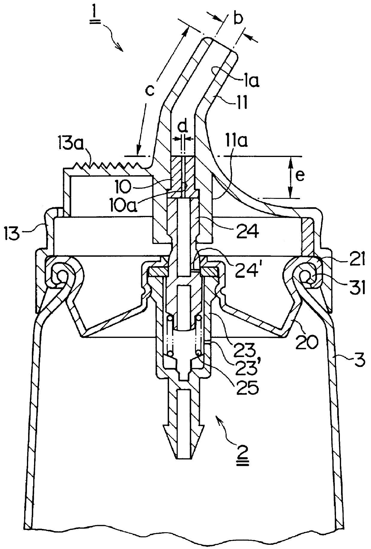
the invention, illustrated in FIG. 1, has a dispensing structure for aerosol containers in which a cup (20) with an aperture is tightly caulked within a container (3), which is filled with an aerosol.

A thin nozzle (10) having a smaller dispensing port (10a) is hermetically inserted into a pipe-shaped spout (1) toward its base end, and a larger dispensing port (1a) is formed toward the tip of the thin nozzle (10).

In the spout (1) described above, the larger dispensing port (1a) may have a bore b of 0.8 to 3 mm, more preferably 1 to 2 mm, and a length c of not less than 5 mm, more preferably between 8 and 40 mm, and the smaller dispensing port (10a) may have a bore d of not more than 0.5 mm, more preferably 0.2 to 0.5 mm, and a length e of 2 to 20 mm, more preferably between 4 and 10 mm.

There is no particular limitation to the choice of the aerosol to fill the container (3), but it may be selected from a great variety of available aerosols; the ingredients of a typical example of aero...

embodiment 2

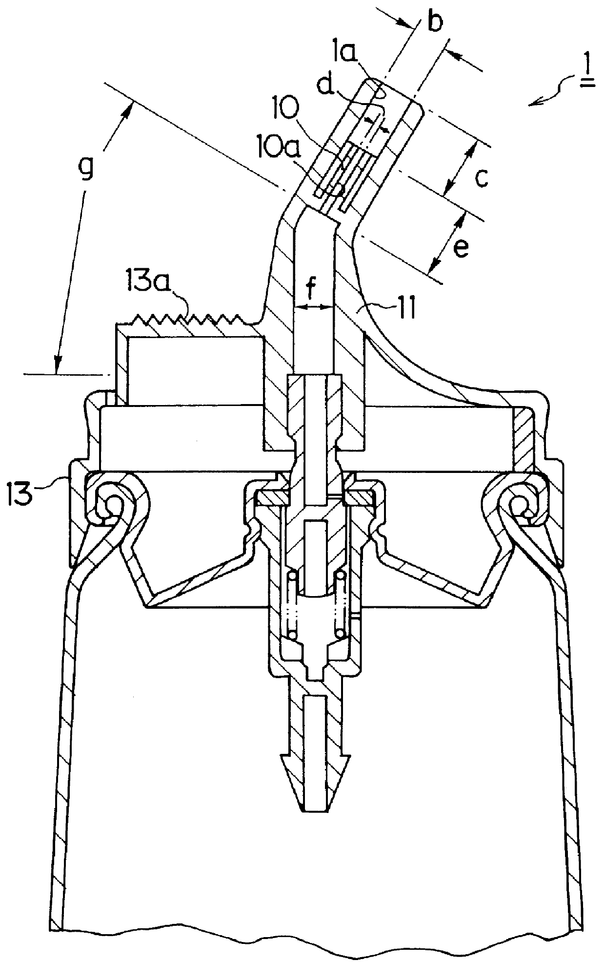
In a dispenser structure for aerosol containers according to the second embodiment of the present invention, illustrated in FIG. 2, a spout (1) has its thin nozzle (10) with a smaller dispensing port (10a) integrally formed in a position ahead of the base end of a dispensing guide (11) toward the tip.

The results of dispensing tests using aerosol containers equipped with the dispensers illustrated in FIGS. 2 and 6 under the same conditions as for Embodiment 1 are stated in Table 2 below as Example 4 and Comparative Example 5.

The results listed in Table 2 above reveal that an aerosol can be dispensed in a satisfactory manner when the dispenser (1) has a smaller dispensing port (10a) with a bore d of not more than 0.5 mm, a larger dispensing port (1a) with a bore b of 0.8 to 3 mm and a length c of not less than 5 mm.

Whereas the dispenser (1) has its thin nozzle (10) with the smaller dispensing port (10a) integrally formed in a position downstream of the base end of the nozzle or dispen...

embodiment 3

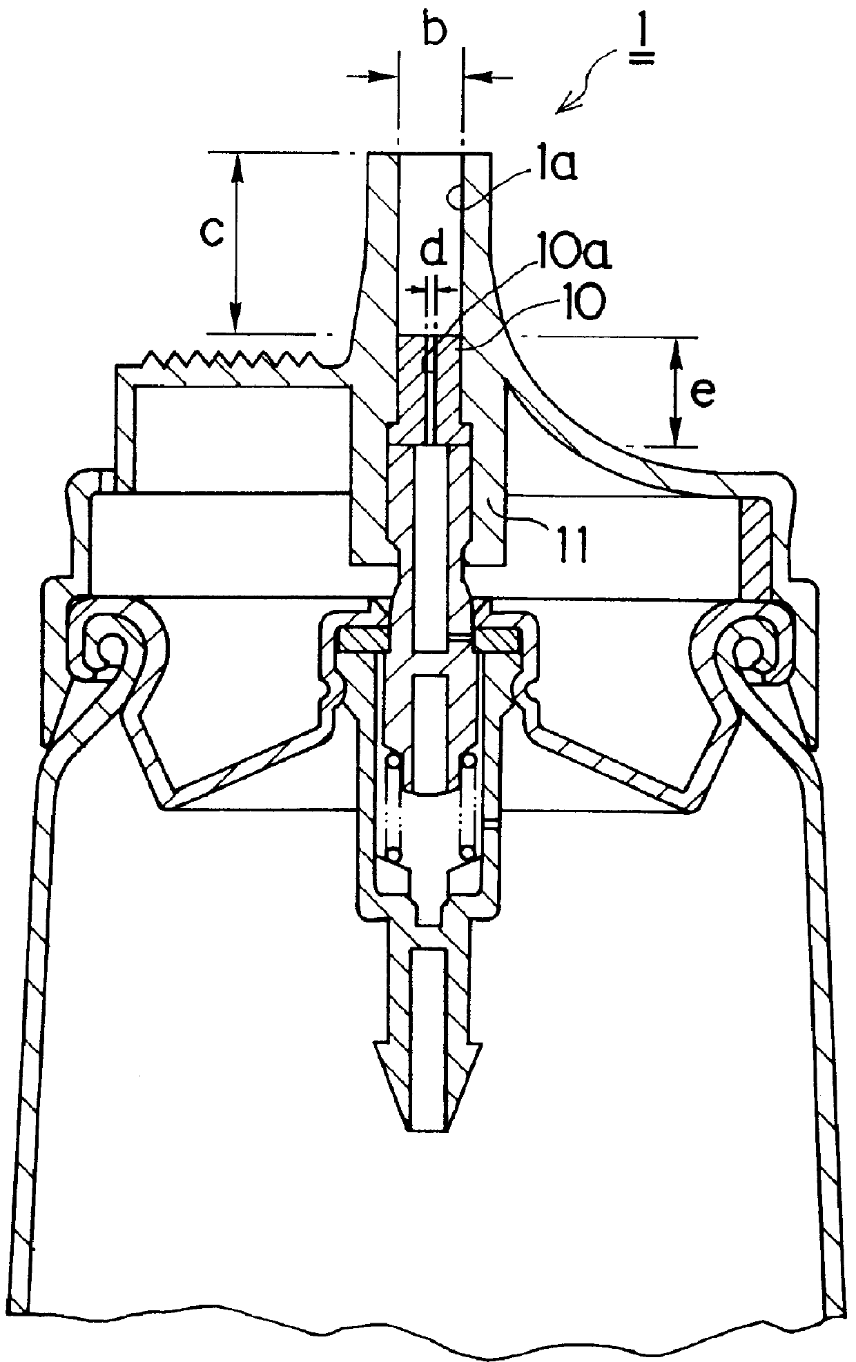
In a dispensing structure for aerosol containers according to the third embodiment of the present invention, illustrated in FIG. 3, a dispenser (1) has its nozzle or dispensing guide (11) formed extending vertically from inside to outside the central part of the top face, and other aspects of the configuration are the same as the first embodiment of the invention.

The results of dispensing tests using aerosol containers equipped with the dispensers illustrated in FIGS. 3 and 7 under the same conditions as for Embodiment 1 are stated in Table 3 below as Examples 5 and 6 and Comparative Examples 6 and 7.

The results listed in Table 3 above reveal that an aerosol can be dispensed in a satisfactory manner when the dispenser (1) has a smaller dispensing port (10a) with a bore d of not more than 0.5 mm, a larger dispensing port (1a) with a bore b of 0.8 to 3 mm and a length c of not less than 5 mm.

As the dispenser (1) has its thin nozzle (10) formed in a vertical direction according to the ...


PUM


Abstract

The present invention is intended to provide a dispenser structure for aerosol containers, which can control the discharge rate of aerosol and ensure satisfactory and safe dispensing of the aerosol while preventing the particle size of the dispensed aerosol from becoming too fine and preventing its excessive scattering which too fine particles would entail. Its structure is characterized in that it includes a dispenser (1) provided with a dispensing guide or first nozzle (11) communicating with a dispensing valve (2); a second nozzle (10) provided within the dispensing guide or first nozzle (11) and having a smaller dispensing port (10a) whose bore d is not more than 0.5 mm; and a larger dispensing port (1a) having a bore b of 0.8 to 3 mm and a length c of not less than 5 mm, formed within the dispensing guide or first nozzle (11) downstream, in the direction of dispensing from the second nozzle (10).

Description

1. Field of the InventionThe present invention relates to a dispensing structure for aerosol containers, and more specifically to a dispensing structure for aerosol containers, designed for satisfactory dispensing of aerosol while controlling the discharge rate of the aerosol contained within.2. Description of the Prior ArtThe basic configuration of an aerosol container to which a dispensing structure according to the prior art is applied will be described below with reference to the accompanying FIG. 4.In the aerosol container according to the prior art, a cup (20) having a dispensing valve (2) at the center is fitted hermetically to the aperture of a container (3) by clinching the cup body (21) together with the curled lip (31) of the container (3).The dispensing valve (2) is formed by inserting a spring (25) through the aperture of a housing (23), fitting a valve stem (24) having a prescribed inside diameter (e.g. .phi. 0.33 mm) into the housing (23) with a prescribed gap in-betw...

Claims


Application Information

Patent Timeline
Patent Type & Authority Patents(United States)
IPC IPC(8): B65D83/14B65D83/16B05B9/04
CPCB65D83/752B65D83/205
Inventor UCHIYAMA, TSUYOSHIIMAOJI, ARIKO
Owner TAISHO PHARMACEUTICAL CO LTD
Why Eureka
Try Eureka