Kit for a rack with a corner connector for vertical frame pieces

a technology of corner connector and vertical frame piece, which is applied in the direction of substation/switching arrangement casing, other domestic articles, substation/switching arrangement framework, etc., can solve the problems of high production cost, high mounting expenditure, and high cost of corner connection types

Inactive Publication Date: 2001-01-16
RITTALWERK RUDOLF LOH GMBH & CO KG
View PDF5 Cites 59 Cited by
  • Summary
  • Abstract
  • Description
  • Claims
  • Application Information

AI Technical Summary

Problems solved by technology

This type of the corner connection is very expensive.
For the individual connectors a high production cost is necessary.
Also the expenditure for mounting is significant since all the vertical frame profiles and the depth and width struts are equipped with the individual parts of the connector.
However, it is not possible to mount or dismount the vertical frame profiles afterwards without the entire rack having to be disassembled in the process.

Method used


Image

  • Kit for a rack with a corner connector for vertical frame pieces
  • Kit for a rack with a corner connector for vertical frame pieces

Examples


Embodiment Construction

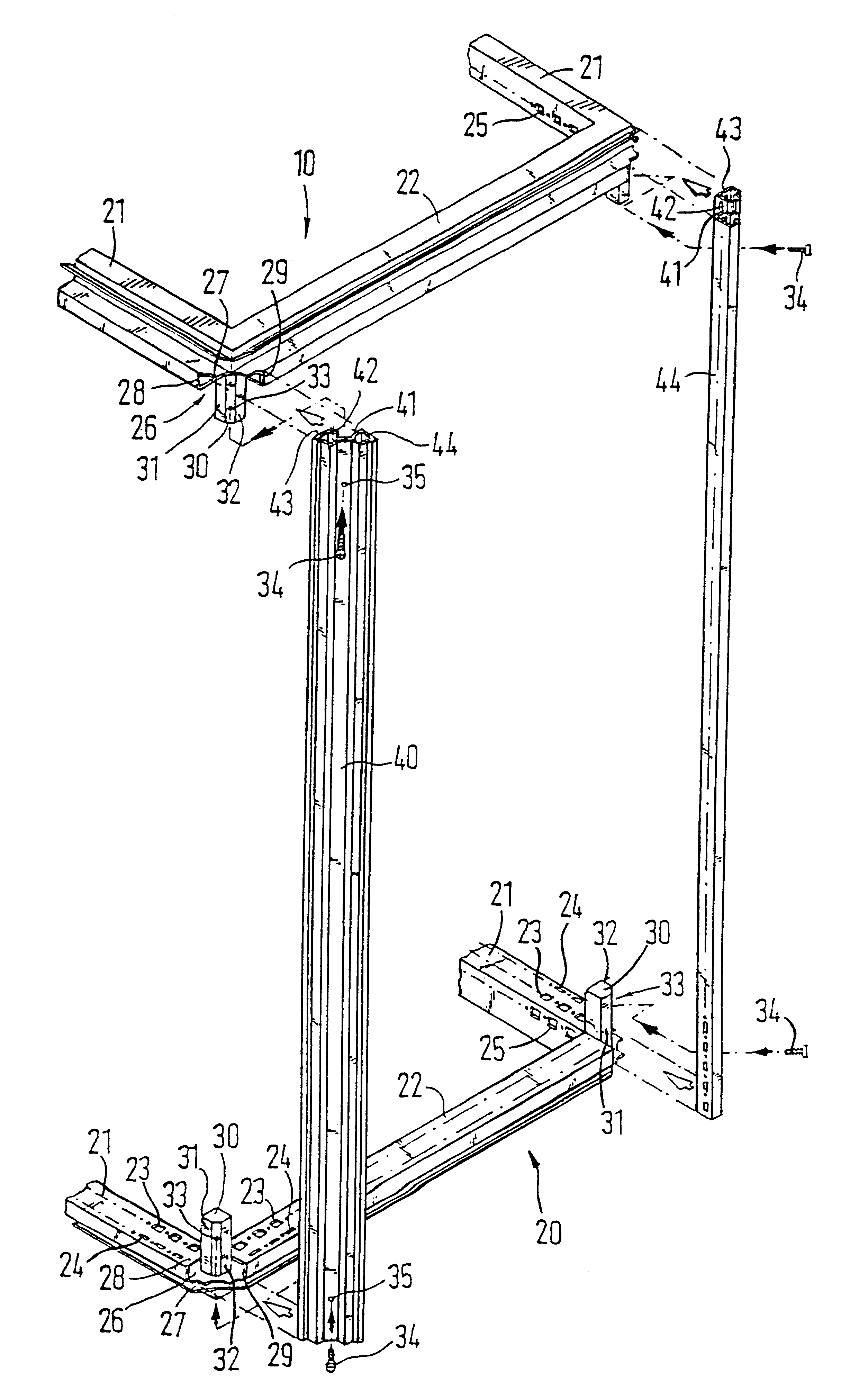
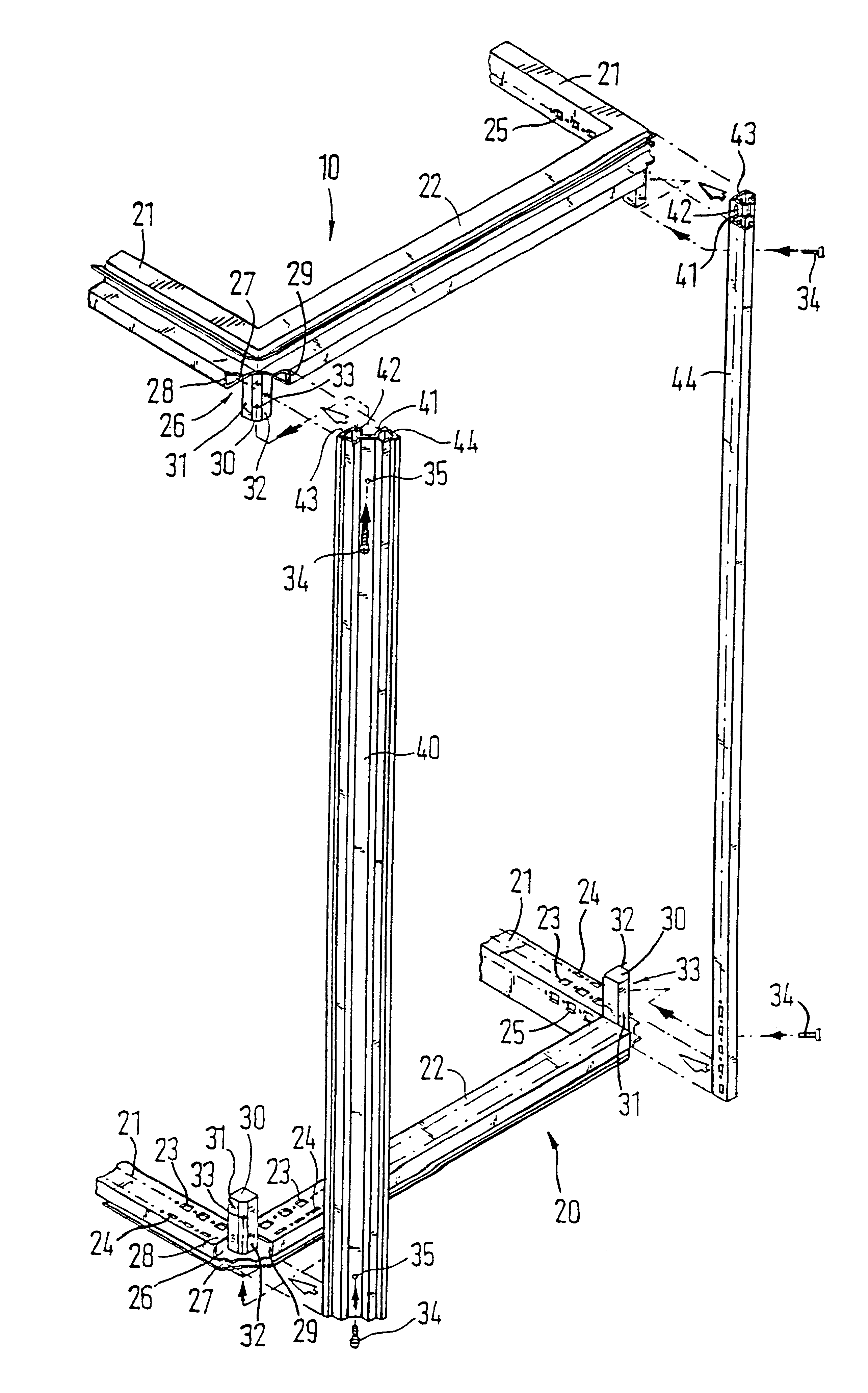
In the single drawing a section of a rack for a switching cabinet is shown in a perspective view. The rack has an upper and lower frame 10 and 20 which can be formed identically so that they can be interchanged. The upper and lower frame 10 and 20 comprise depth and width struts 21 and 22 running perpendicular to one another. The depth and width struts 21 and 22 have, turned towards the inside of the rack, two profiled sides which have rows 23, 24, and 25 of fastening holes. The rows 23, 24, and 25 of fastening holes are spaced from one another at equal intervals.

Corner cavities 26 are formed at the mutually abutting ends of the depth and width struts 21 and 22. The corner cavities 26 have a plane supporting surface 27 on which the one connector 30 is set. The connector 30 is essentially formed as a square. At one of its vertical edges the connector 30 has a bevel into which one or more threaded holes 33 are introduced. The bevel points to the outer side of the rack. For fastening, ...


PUM


Abstract

A switching cabinet having a rack with an upper and lower frame and vertical and horizontal struts which are disposed horizontally. The upper and lower frame have corner cavities, to which vertical frame profiles can be connected. The vertical frame profiles have profiled segments which are turned towards an inside of the rack. Access to the inside of the rack is improved when the vertical frame profiles may be mounted or dismounted afterwards which can be done with few components and involves little effort during mounting by including vertical profiles on at least one side of the rack, whose ends and profiled segments can be inserted into the corner cavity from the outer side of the rack, and by placing and fixing the profiled segments onto the connector of a corner cavity.

Description

1. Field of the InventionThis invention relates to a switching cabinet with a rack which has a lower and upper frame with horizontal width and depth struts wherein the lower and the upper frame have corner cavities wherein vertical frame profiles can be attached and wherein the vertical frame profiles have profiled parts turned toward the inside of the rack.2. Description of Prior ArtSuch a frame is known from European Patent Reference EP 0 533 555 B1. The vertical frame profiles are formed as hollow profiles. To form a rack individual frame profiles are assembled adjacent to one another at ends by corner connectors. The corner connectors have various individual parts. Each pair of depth and width struts of the lower and upper frame are connected perpendicularly to one another of one of these individual parts. Additional individual parts are installed in the hollow chambers with connecting plugs running in the longitudinal direction of the frame profiles and fixedly connected to the...

Claims


Application Information

Patent Timeline
Patent Type & Authority Patents(United States)
IPC IPC(8): H02B1/30H02B1/00H02B1/01H05K7/18H02B1/32
CPCH02B1/301H02B1/013H02B1/014
Inventor BENNER, ROLFKOHLER, MARTINAMUNCH, UDOREUTER, WOLFGANG
Owner RITTALWERK RUDOLF LOH GMBH & CO KG
Why Eureka
Try Eureka