Cartridge case former and method

a cartridge case and former technology, applied in the field of cartridge cases for guns, can solve the problems of laborious resizing, high cost, and high cost of resizing, and achieve the effects of improving the quality of resizing, and improving the accuracy of resizing

Inactive Publication Date: 2001-02-27
BENNETT RONALD B
View PDF22 Cites 24 Cited by
  • Summary
  • Abstract
  • Description
  • Claims
  • Application Information

AI Technical Summary

Problems solved by technology

However, some gun operators desire non-standard or "special" cartridges for shooting.
Although the above special cartridge cases have worked well, they suffer ...

Method used


Image

  • Cartridge case former and method
  • Cartridge case former and method
  • Cartridge case former and method

Examples


Embodiment Construction

)

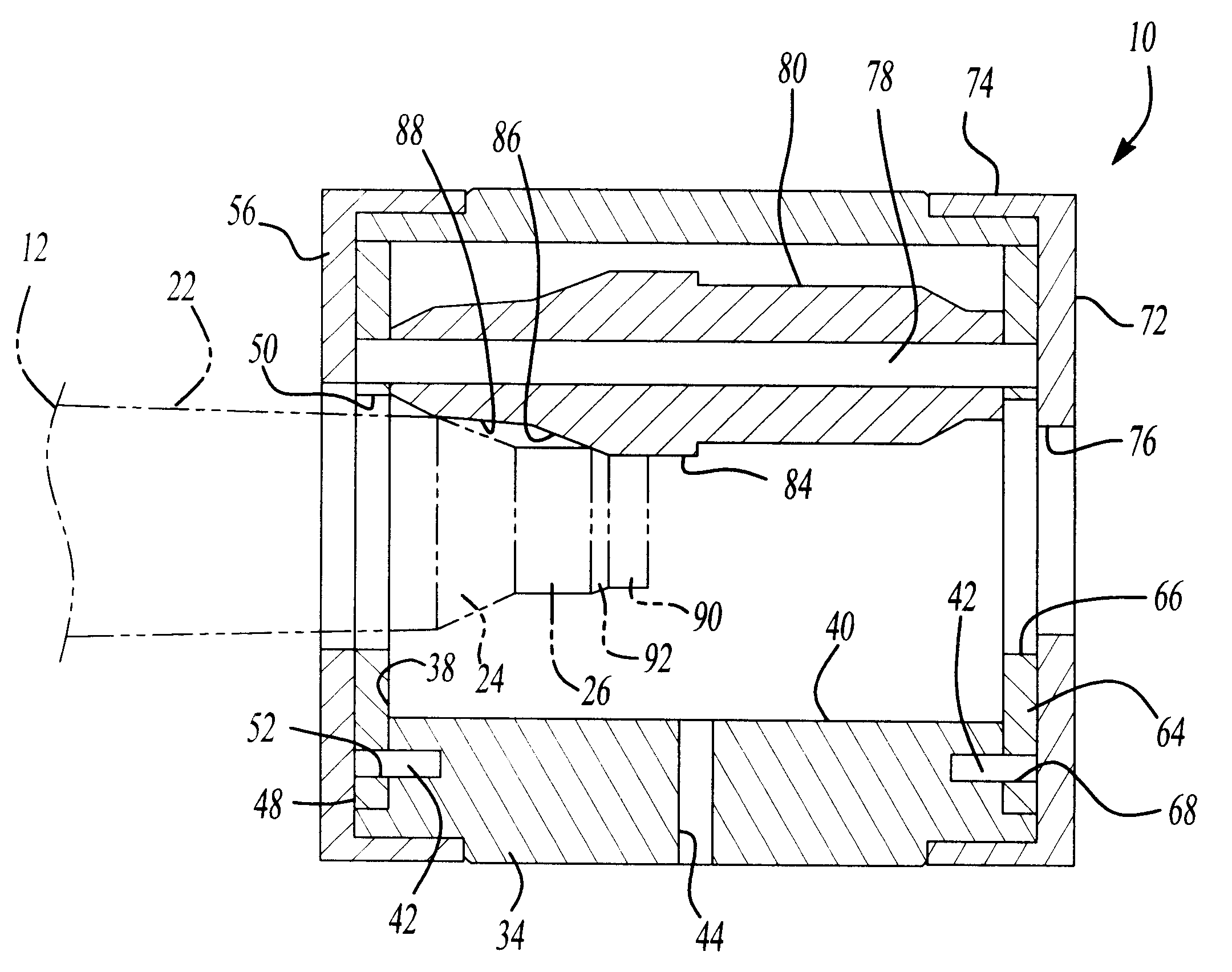
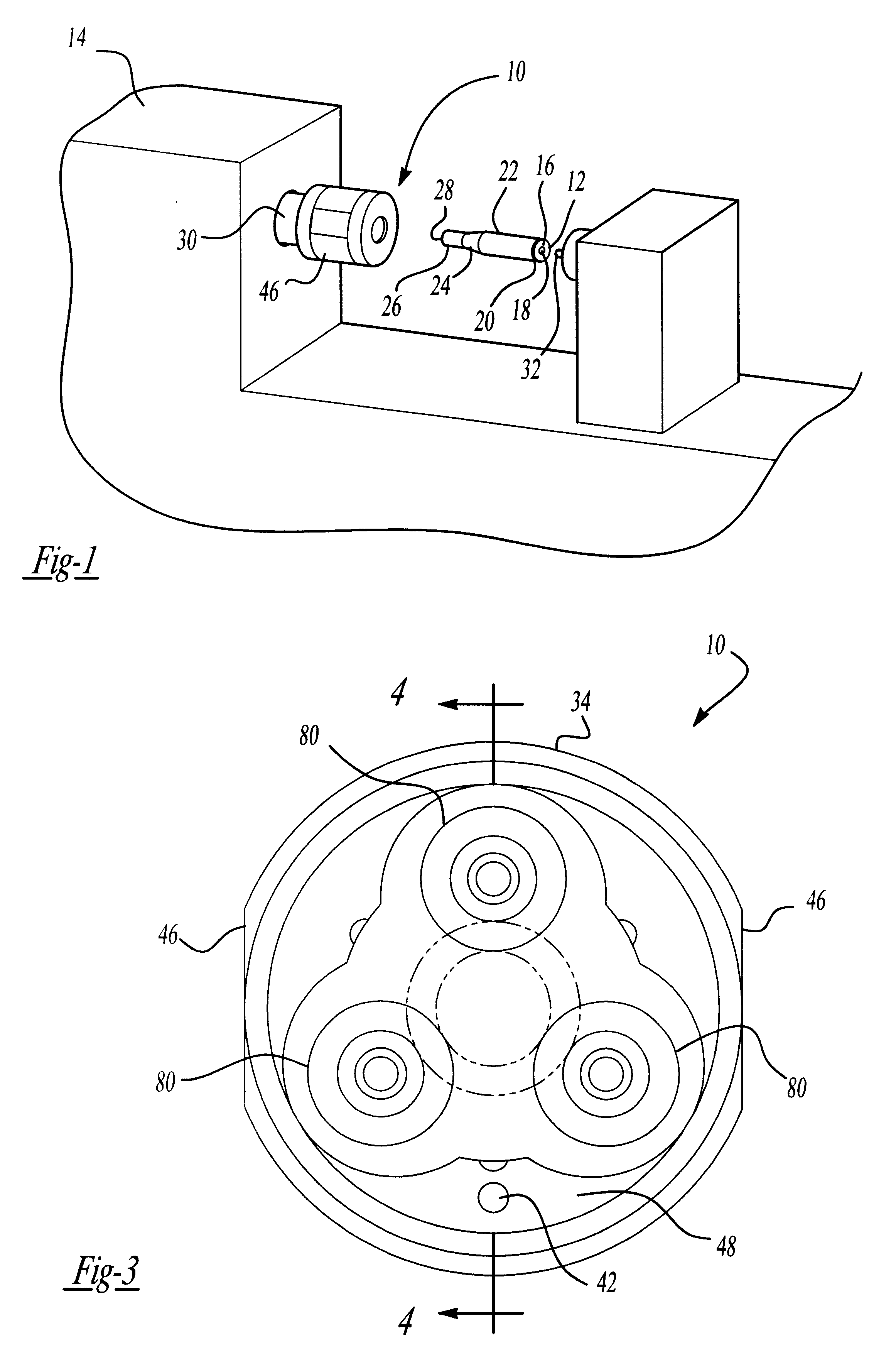
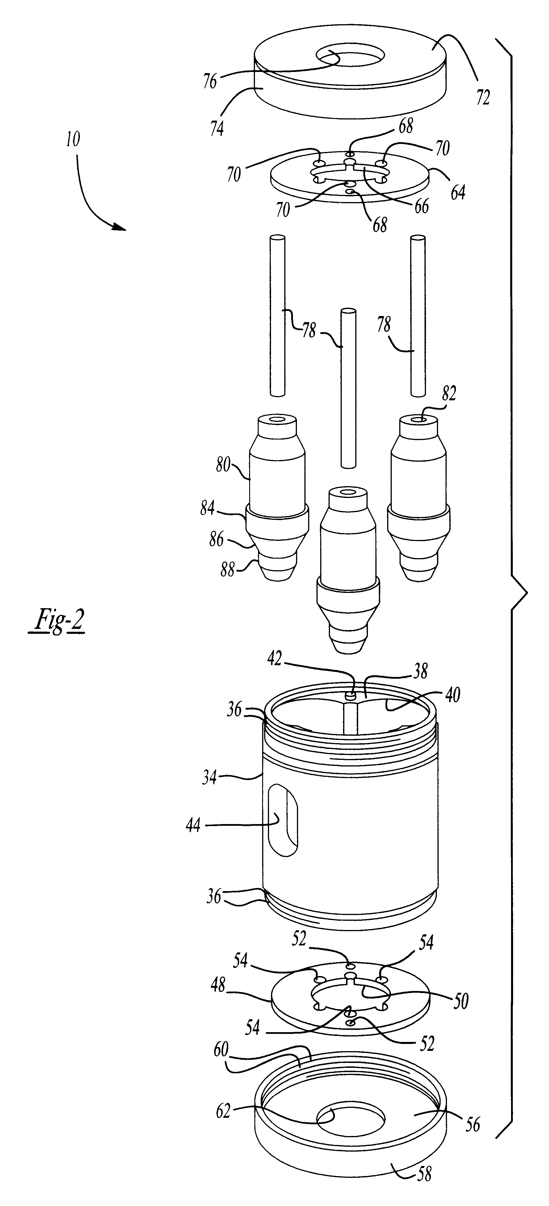
Referring now to the drawings and in particular to FIG. 1, one embodiment of a cartridge case former 10, according to the present invention, is illustrated in operational relationship with a cartridge case 12 and lathe 14. The cartridge case 12 is generally cylindrical in shape and made of a metal material such as brass. The cartridge case 12 includes a rim 16 having a primer pocket 18, an extractor groove 20, a body 22, a tapered shoulder 24, a neck 26 and a mouth 28. It should be appreciated that the cartridge case 12 is of a standard size in the art. It should also be appreciated that, prior to forming with the cartridge case former 10, the cartridge case 12 is conventional and known in the art.

The lathe 14 includes a headstock 30 such as a chuck, which is rotated by a source (not shown), of the lathe 14. The lathe 14 also includes a tailstock 32 such as a center. The cartridge case former 10 is mounted to the headstock 30 and the cartridge case 12 is mounted to the tailstock 32...


PUM

PropertyMeasurementUnit
Diameteraaaaaaaaaa
Sizeaaaaaaaaaa

Abstract

A cartridge case former and method includes a front arbor plate, a rear arbor plate and a plurality of arbors extending between the front arbor plate and the rear arbor plate. The cartridge case former also includes a plurality of rotatable roller dies disposed about the arbors for forming a neck of a cartridge case.

Description

1. Field of the InventionThe present invention relates generally to cartridges for guns and, more particularly, to a cartridge case former and method of forming a cartridge case for a cartridge.2. Description of the Related ArtIt is known to provide cartridges for guns. Typically, the cartridge includes a cylindrical case made from a brass cylinder, which has a rim with a primer pocket, extractor groove, body, tapered shoulder, neck and mouth. The cartridge also includes a primer disposed in the primer pocket, powder disposed within the body and a bullet disposed in the end of the neck.The cartridge cases are manufactured in standard sizes. However, some gun operators desire non-standard or "special" cartridges for shooting. To make such cartridges, a standard cartridge case is put into a cartridge-resizing die and the neck is expanded or contracted. The neck may then be reamed internally or externally with a reamer to a desired size.Although the above special cartridge cases have w...

Claims


Application Information

Patent Timeline
IPC IPC(8): B21D41/00B21D41/04F42B33/00F42B33/10
CPCB21D41/04F42B33/10
Inventor BENNETT, RONALD B.
Owner BENNETT RONALD B
Why Eureka
Try Eureka