Glass workpiece locating system

a technology of workpiece locating and glass, which is applied in the direction of grinding machine components, stock shearing machines, manufacturing tools, etc., can solve the problems of increasing the likelihood of damage to specific workpieces, time-consuming and complex positioning systems,

Inactive Publication Date: 2001-03-20
BILLCO MFG
View PDF29 Cites 42 Cited by
  • Summary
  • Abstract
  • Description
  • Claims
  • Application Information

AI Technical Summary

Problems solved by technology

Additionally, the transverse movement of the glass workpiece in these prior art systems increases the likelihood of damage to the specific workpiece.
This system represents a time-consuming and complex positioning system.

Method used


Image

  • Glass workpiece locating system
  • Glass workpiece locating system
  • Glass workpiece locating system

Examples


Embodiment Construction

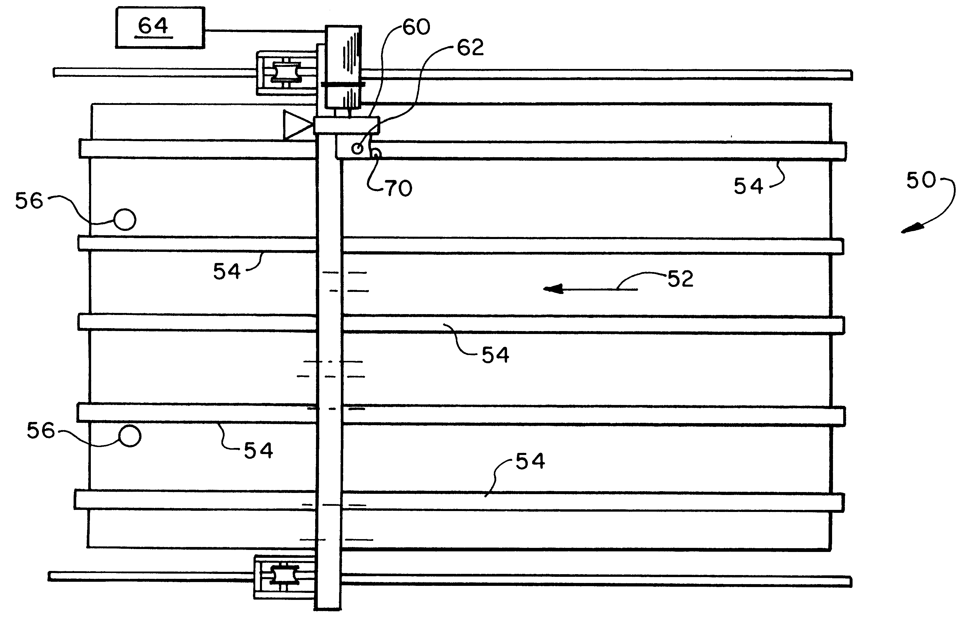
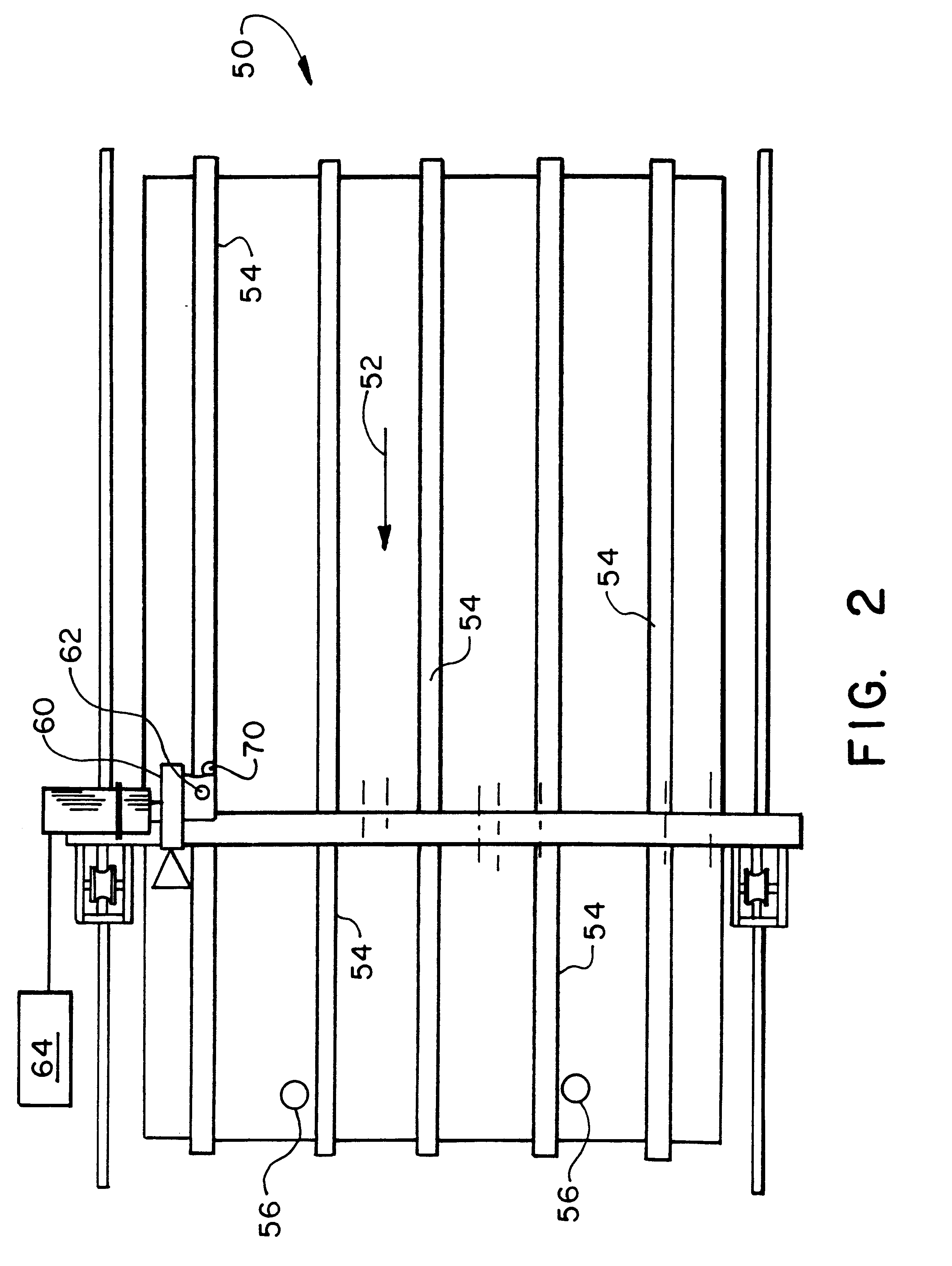
A glass workpiece positioning system according to the present invention is illustrated in the glass workpiece cutting table 50 shown in FIG. 2. The cutting table 50 includes a conveyor for receiving, transporting and supporting a rectangular glass workpiece in a transporting direction 52. The conveyor is formed by a plurality of substantially parallel conveyor belts 54 which are adapted to receive and transport a rectangular glass workpiece in the transporting direction 52 which is substantially parallel to the conveyor belts 54. Additionally, the conveyor belts 54 may be conventionally driven by a common drive. Stop mechanism 56 is formed by a pair of pneumatically actuated, retractable stop members which are positioned at one end of the cutting table 50 and are aligned substantially perpendicular to the transporting direction 52 and substantially perpendicular to the conveyor belts 54.

A cutting head assembly 60 is provided for movement over the cutting table 50 in a conventional f...


PUM

PropertyMeasurementUnit
dimensionsaaaaaaaaaa
movementaaaaaaaaaa
timeaaaaaaaaaa

Abstract

A rectangular glass workpiece positioning system and method of use for a cutting table is disclosed. A conveyor transports a rectangular glass workpiece in a transporting direction. A stop mechanism is adapted to abut an edge of the glass workpiece which is positioned substantially perpendicular to the transporting direction of the conveyor. A movable edge sensor is adapted to sense an edge of the glass workpiece extending substantially parallel to the transporting direction with the movable edge sensor movable at least perpendicular to the transporting direction. A movable cutting head is provided for cutting the glass workpiece according to a predetermined pattern. The present invention additionally includes a method of retrofitting existing cutting tables.

Description

1. Field of the InventionThe present invention relates to a glass workpiece locating system and method for locating a rectangular glass workpiece on a cutting table. The present invention further relates to a method of retrofitting existing cutting tables with the positioning system of the present invention.2. Prior ArtFIG. 1 illustrates a conventional cutting table 10 which is utilized for locating, squaring and cutting a rectangular glass workpiece having known dimensions. The conventional method of locating and squaring a rectangular workpiece on the cutting table 10 is to transport the workpiece in a transporting direction 12 by conveyors 14. The workpiece is conveyed in the transporting direction 12 until the workpiece abuts a first pair of stops 16. Upon contact between the workpiece and the first pair of stops 16, the conveyors 14 are stopped, and the workpiece is transported subsequently transversely to the transporting direction 12 against a second pair of stops or locators...

Claims


Application Information

Patent Timeline
Patent Type & Authority Patents(United States)
IPC IPC(8): C03B33/00C03B33/03
CPCC03B33/03Y10T83/04Y10T83/0605Y10T83/145Y10T83/155Y10T83/178Y10T83/4664Y10T83/541Y10T83/5815Y10T83/6577
Inventor CUNNINGHAM, DENNIS J.
Owner BILLCO MFG
Why Eureka
Try Eureka