Land mine killer

a technology for killing land mines and mines, applied in the field of land mine killing, can solve the problems of presenting a considerable danger to travelers, animals and particularly small children, anti-tank mines and unexploded bombs, and a greater problem for vehicular traffic, and most importantly to large and costly mine removal equipmen

Inactive Publication Date: 2001-03-20
UNITED STATES OF AMERICA THE AS REPRESENTED BY THE SEC OF THE ARMY
View PDF9 Cites 7 Cited by
  • Summary
  • Abstract
  • Description
  • Claims
  • Application Information

AI Technical Summary

Problems solved by technology

Recently, there has been a proliferation of land mines and armed munitions with faulty fuzes in certain countries which presents a considerable hazard to travelers, animals and particularly small children.
As yet these objects contain no self-destruct capability.
Though less in number, anti-tank mines and unexploded bombs present

Method used


Image

  • Land mine killer
  • Land mine killer
  • Land mine killer

Examples


Embodiment Construction

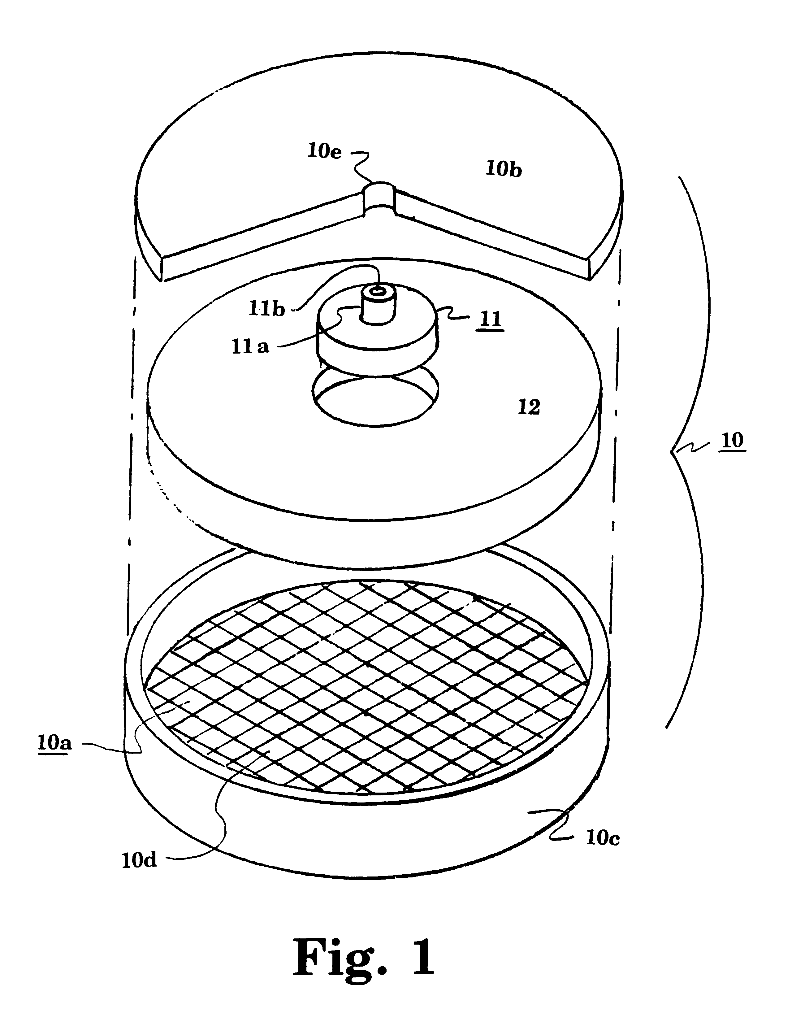
Referring again to the drawings, and more particularly to FIG. 1, there is shown an isometric view of one embodiment of an MK round according to the present invention. This round 10 has a hollow disk shaped body defined by a broad circular bottom plate 10a, a similar top plate 10b and a toroidal sidewall 10c. The bottom plate is grooved to define explosively formed projectiles (EFP) 10d, that fire away from the thicker opposite ungrooved top plate of the body when a fuze 11 detonates an explosive charge 12 inside the body. The fuze, similar to many available for artillery, incorporates a time delay that allows the round to just reach its destination in the mine field before detonating the charge. The top plate defines an aperture 10e to receive a stem 11a projecting axially from the fuze. The time is set through this stem by mechanical or electrical timing mechanisms well known in the art. If the timing mechanism is mechanical, the stem will be shaped to receive a timing tool, such ...


PUM


Abstract

A mine destroyer round in the shape of a hollow aerodynamic disk containing explosively formed projectiles that fire toward the ground. A powered means such as a catapult or a mortar tube containing a contact explosive is used to launch the round over a mine field.

Description

DESCRIPTION1. Field of the InventionThe present invention generally relates to methods and devices for clearing combat areas of unexploded mines and other munitions.2. Description of the Prior ArtRecently, there has been a proliferation of land mines and armed munitions with faulty fuzes in certain countries which presents a considerable hazard to travelers, animals and particularly small children. As yet these objects contain no self-destruct capability. The largest population of mines are of the anti-personnel type, which more often maim than kill. Though less in number, anti-tank mines and unexploded bombs present a greater problem to vehicular traffic and most importantly to large and costly mine removal equipment. The easiest method of removing anti-personnel mines is a lightly armored rake, that does not have to penetrate deeply into the ground. This, however is much too dangerous when more deeply buried anti-tank mines, some using shaped charges, are also present. Another pro...

Claims


Application Information

Patent Timeline
IPC IPC(8): F42C19/08F42C19/00F42B33/00F42C17/00F42C17/04F42B33/06F41H11/00F41B4/00F42B12/02F41H11/12F42B12/24
CPCF41B4/00F41H11/12F42B6/00F42B12/24F42B33/06F42C17/04F42C19/0846
Inventor COMEYNE, WILLIAM G.
Owner UNITED STATES OF AMERICA THE AS REPRESENTED BY THE SEC OF THE ARMY
Why Eureka
Try Eureka