Flooring panel

Inactive Publication Date: 2001-04-03
KRONOTEX
View PDF7 Cites 353 Cited by
  • Summary
  • Abstract
  • Description
  • Claims
  • Application Information

AI Technical Summary

Problems solved by technology

This results in the inability to again separate the two connecting members by simple linear sliding.
However, a problem with such prior art connecting members is that a previously laid flooring panel must be significantly raised when joining additional flooring panel.
This is due to the fact that the previously laid flooring panel is usually connected with other panels thereby making it difficult to raise from the sub-floor.
It is also noted that the connecting member may be damaged since there may be too much stress on the lower projection and/or the tongue.
As a further problem, high strains may be created on both connecting members in the lower region between the lower projection of the first connecting member and the tongue of the second connection member subsequent to the installation thereof This is because high strain is directed

Method used


Image

  • Flooring panel
  • Flooring panel
  • Flooring panel

Examples


Embodiment Construction

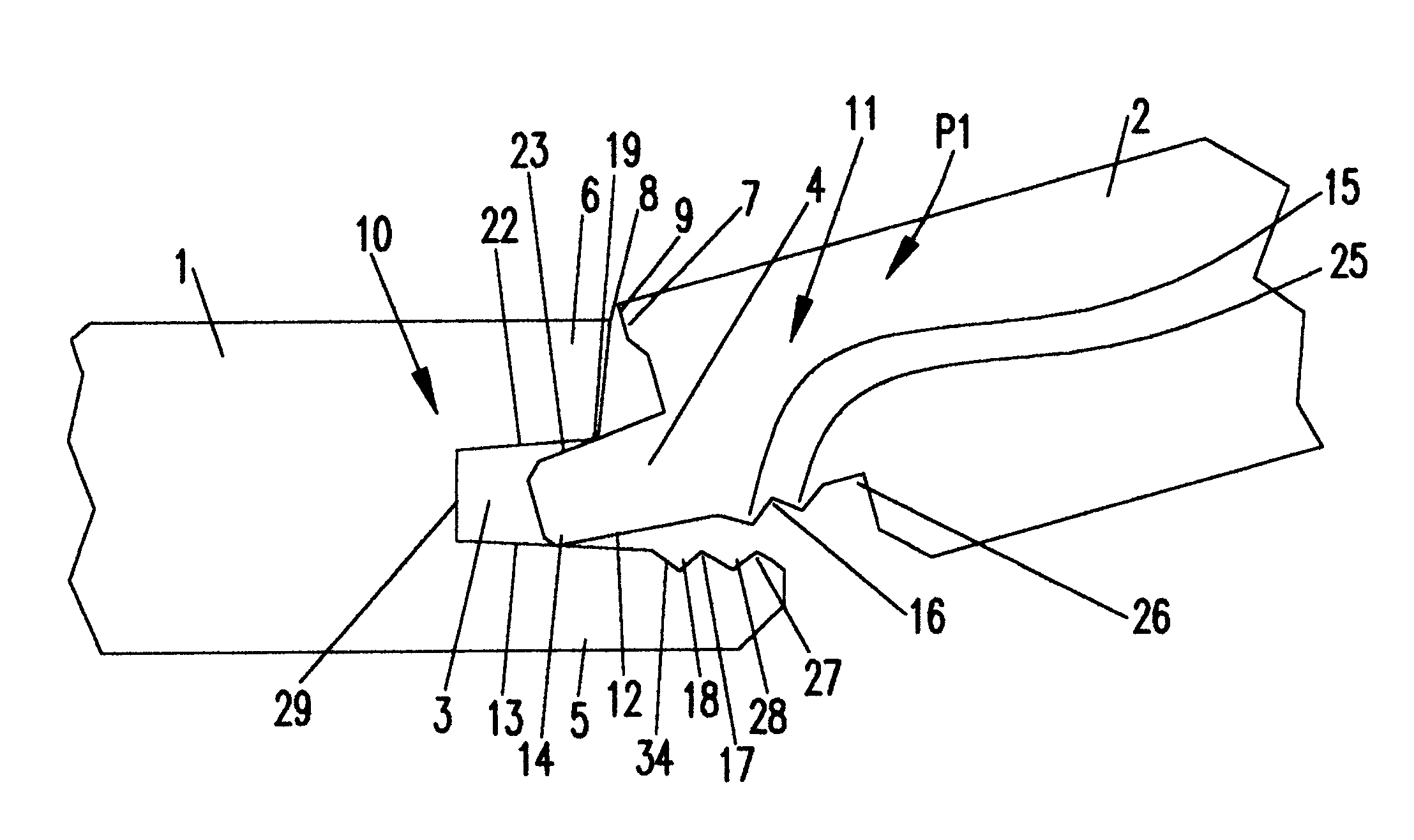
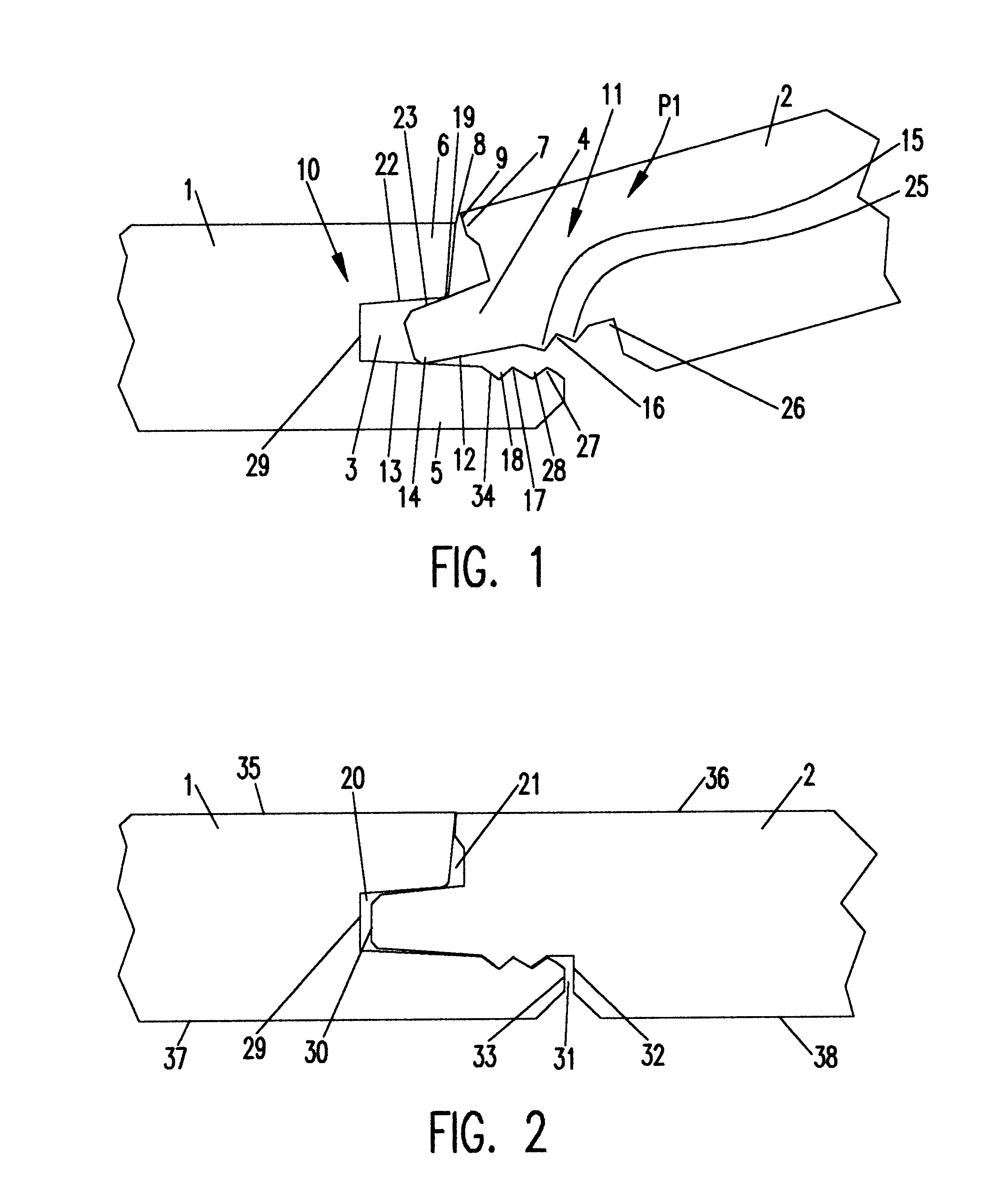
Referring now to the drawings, and more particularly referring to FIG. 1, there is shown a connection panel 1 which includes a first connection member 10 and on the opposite side a second connection member 11. Both connection members 10 and 11 are shaped so that they are appropriate for face-to-face engagement with each other, as is shown in FIGS. 1 and 2.

The first connection member 10 of flooring panel 1 has an upper projection 6, a lower projection 5, as well as a groove 3 between the projections 5 and 6. An installation ledge 8 is formed on the upper end of the upper projection 6. The groove 3 shows a groove-base 29 limited by the upper side 13 of the lower projection 5 and the lower side 22 of the upper projection 6, whereby the lower side 22 of the upper projection 6 and the upper side 13 of the lower projection 5 are slanted towards the groove-base 29. This configuration results in the groove 3 being tapered toward the groove-base 29.

At the outer end of the lower projection 5 ...


PUM

PropertyMeasurementUnit
Heightaaaaaaaaaa
Deformation enthalpyaaaaaaaaaa

Abstract

Flooring panel with two connection members whose sides face each other for attachment to other flooring panels of the same type. A first connection member has an upper projection, a lower projection, and groove between them. A second connecting member features a tongue for insertion in the groove of an adjacent connection member. In order to achieve good assembly as well as economical production of the panels, provision is made for a lower protuberance, lower indentation, lower auxiliary protuberance, and lower auxiliary indentation on the lower projection of the first connection member. The profile thus created is fitted to a corresponding profile on the lower side of the tongue which has an upper indentation, an upper protuberance, an upper auxiliary indentation, and an upper auxiliary protuberance.

Description

1. Field of the InventionThe present invention generally relates to flooring panels and, more particularly, to flooring panels having connection members for simply and effectively installing adjacent flooring panels to one another.2. Background DescriptionWO 97 / 47384 A1 shows flooring panels in FIGS. 5-7 and FIGS. 22-25. Specifically, these flooring panels may be connected to one another without, for example, the need to glue them to the sub-floor or connecting them with additional connection devices such as tracks. The connection members of two flooring panel can thereby be joined parallel to the sub-floor by linearly sliding them into each other; however, in order to achieve a seamless joint between the connection members the lower projection of the first connection member must be bent downwards during the connecting process and, due to its elastic properties, snap back to its original configuration thereby catching the upper projection on the under side of the tongue. This result...

Claims


Application Information

Patent Timeline
IPC IPC(8): E04F15/04F16B5/00E04F15/02
CPCE04F15/04F16B5/008E04F2201/0115E04F2201/0153B29C48/07B29C48/0011
Inventor TYCHSEN, DETLEF
Owner KRONOTEX
Why Eureka
Try Eureka