
Lock

a technology of locking bolts and latches, applied in the field of locks, can solve problems such as unintentional removal of holding bolts, and achieve the effect of preventing unintentional removal

Inactive Publication Date: 2001-04-10
SOUTHCO
View PDF10 Cites 1 Cited by
  • Summary
  • Abstract
  • Description
  • Claims
  • Application Information

AI Technical Summary

Benefits of technology

The first object stated above has been achieved in a lock including a lock case, a forend attachable to said case by means of removable fastening means, a latch bolt movable within said case between a locking position, in which it at least partly projects from the case, and an unlocking position, in which it is retracted within the case, a holding bolt having a defined cross section and being positionable in a first, relatively retracted position allowing movement of said latch bolt from its locking position to its unlocking position, and in a second relatively inserted position preventing movement of said holding bolt from its locking position to its unlocking position, and spring means for yieldably retaining said holding bolt in its first and second positions and for positively preventing withdrawal thereof from said case, wherein at least one portion of said spring means is movable between a first position, in which it prevents withdrawal of said holding bolt, and a second position, in which it allows withdrawal of said holding bolt, movement of said at least one portion from said first to said second position being enabled by at least partial removal of said fastening means.

Problems solved by technology

However, withdrawal of the holding bolt is possible upon manually rotating it through a small, limited angle against the action of the spring.

Method used


Image

  • Lock
  • Lock
  • Lock

Examples


Embodiment Construction

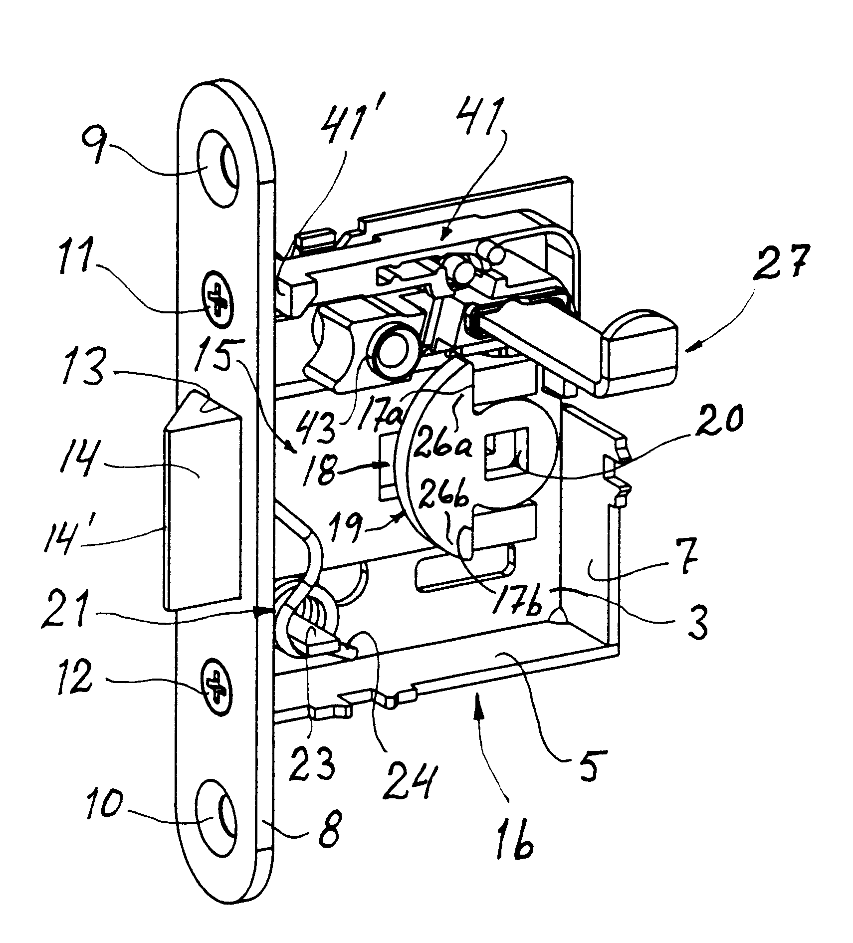
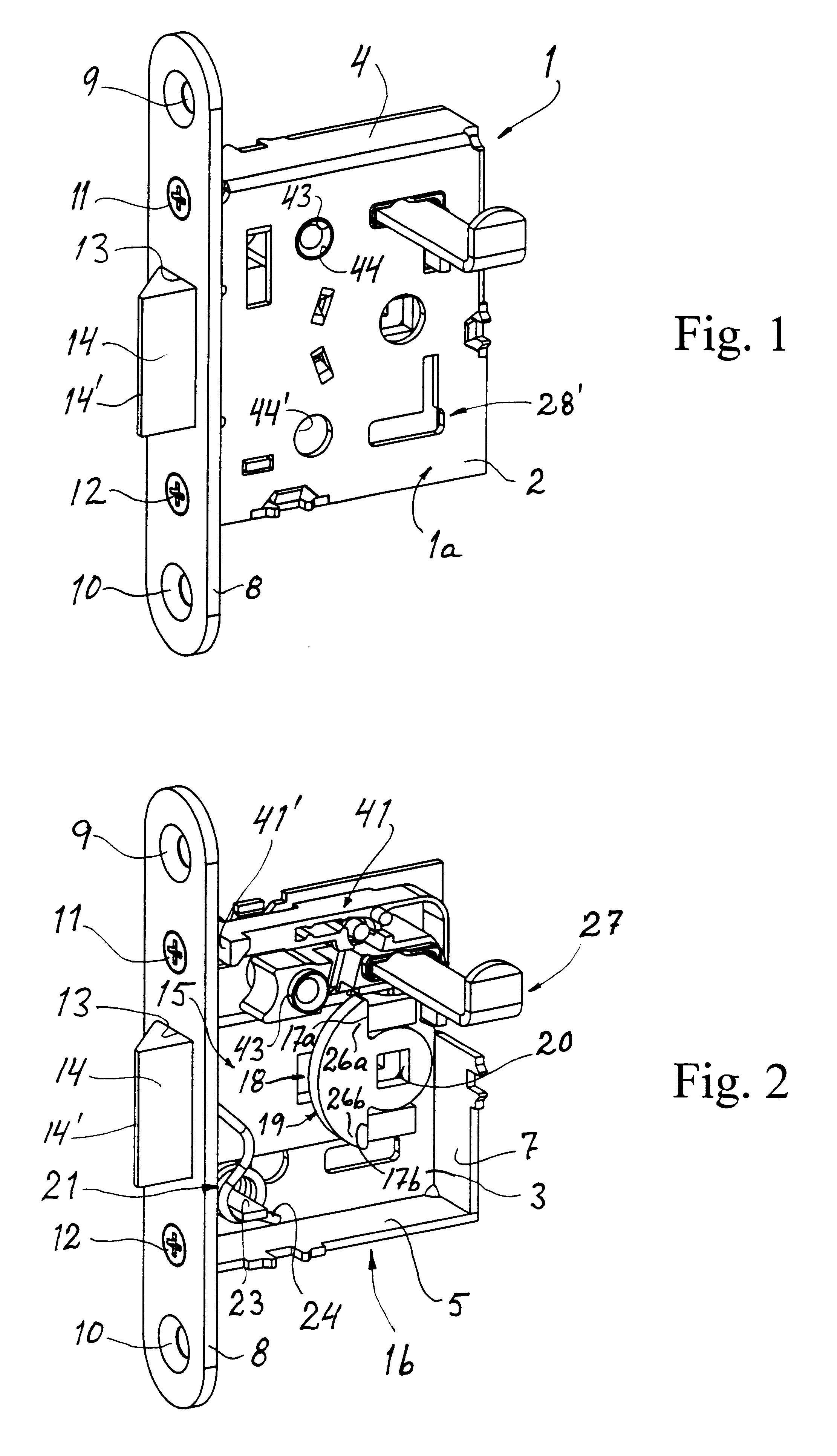
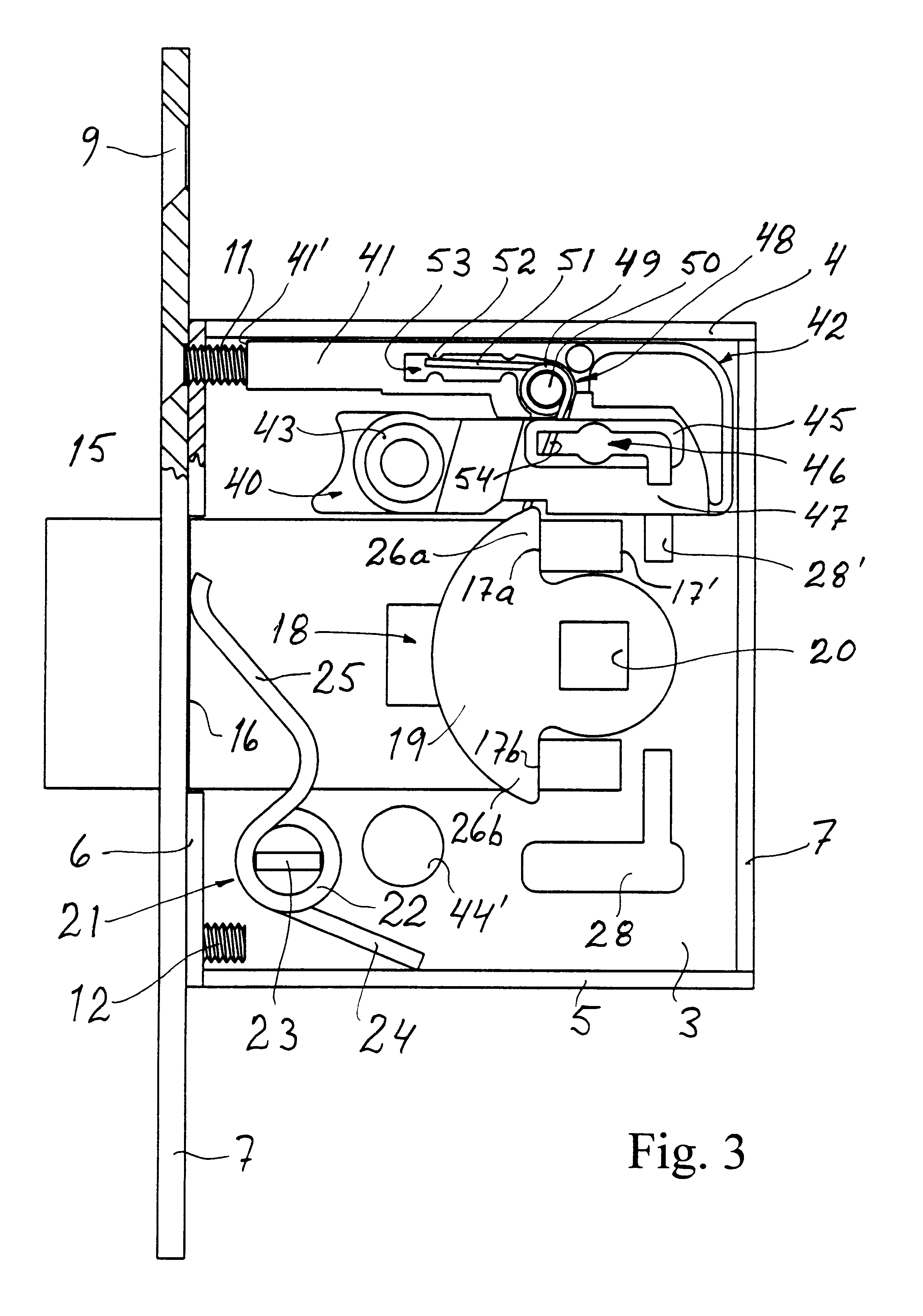
The lock according to the present invention has a lock case 1 consisting of two equal halves 1a, 1b. The case includes two opposed side walls 2 and 3, an upper wall 4, a lower wall 5, a front wall 6 and a back wall 7. A forend 8 has two holes 9 and 10 for attachment of the lock to, e.g., a door leaf. Two screws 11 and 12 attach the forend to the front wall 6. The forend also has a rectangular opening 13 through which a latch bolt 14 is slidable between a foremost, locking position, in which it projects from the case, as seen in FIGS. 1, 2 and 3, and a non-shown, unlocking position, in which it is backwardly retracted within the case so as to leave its front edge 14' substantially flush with the forend 8. The latch bolt has a recessed portion 15 forwardly defined by a shoulder 16 (FIG. 3). In the backward direction a corresponding shoulder is divided in two shoulders 17a, 17b separated by a slot 18 extending from the backward end of the latch bolt about half way to its forward end.

Th...


PUM


Abstract

A lock has a holding bolt and a retaining member for yieldably retaining the holding bolt in its bolting and its release position and for positively preventing the bolt from withdrawal from the lock unless a fastening member attaching a forend of the lock to the lock case is at least partly released.

Description

1. Field of the InventionThe present invention concerns a lock having a bolting means for bolting a latch bolt.2. Description of the Background ArtMore precisely, this invention concerns a lock installable in, e.g., a door leaf. The lock includes a case and a latch bolt movable within the case between a locking position, in which the latch bolt at least partly projects from the case, and an unlocking position, in which the latch bolt is retracted within the case. Generally, a lock of this kind includes some kind of bolting means adapted to bolt the latch bolt in at least its locked position. Such bolting means is generally factory mounted on one side of the case for access from a corresponding side of a door. Consequently, to comply with possible customer needs, it is necessary to manufacture two locks having the bolting means on opposite sides of the case.U.S. Pat. No. 5,779,287 discloses a lock having an optional bolting means, i.e., a bolting means that is separately delivered wi...

Claims


Application Information

Patent Timeline
Patent Type & Authority Patents(United States)
IPC IPC(8): E05B15/12E05B15/00E05B9/00E05B9/02E05B55/00E05B63/00E05B63/04
CPCE05B9/02E05B17/2023E05B55/00E05B63/04Y10S292/64Y10T292/0971
Inventor MAGNUSSON, CLAES
Owner SOUTHCO
Learn More