
Wire unit

a wire unit and wire technology, applied in the direction of pipe supports, fastening means, electrical apparatus, etc., can solve the problems of inability to ensure the work space, the above configuration cannot be applied in an environment in which such work space cannot be guaranteed, and the task is complicated and burdensome, so as to achieve smooth support surface, space constraints are further reduced, and the diameter and shape of the electrical wires are not entirely constant.

Active Publication Date: 2020-05-14
SUMITOMO WIRING SYST LTD
View PDF0 Cites 1 Cited by
  • Summary
  • Abstract
  • Description
  • Claims
  • Application Information

AI Technical Summary

Benefits of technology

This patent is about a device that helps to keep electrical wires securely in place on a support surface. The device is made up of a wire member that is twisted and tied together to form a retaining member. The retaining pieces are collapsible from a standing position to a retaining position to prevent interference with the support surface and to keep the wires in place. The retaining pieces can be bent and deformed in different directions to make it easier to insert and retain the wires. The twisting process makes the retaining member lighter and more adjustable, and the disposed portions of the retaining pieces do not project too far from the support surface, reducing space constraints.

Problems solved by technology

These tasks are complicated and burdensome.
However, the work space for inserting the electrical wires from a sideward direction into the gap between the pressing piece and the support surface is necessary.
The above configuration cannot be applied in an environment in which such work space cannot be ensured.

Method used


Image

  • Wire unit
  • Wire unit
  • Wire unit

Examples


first embodiment

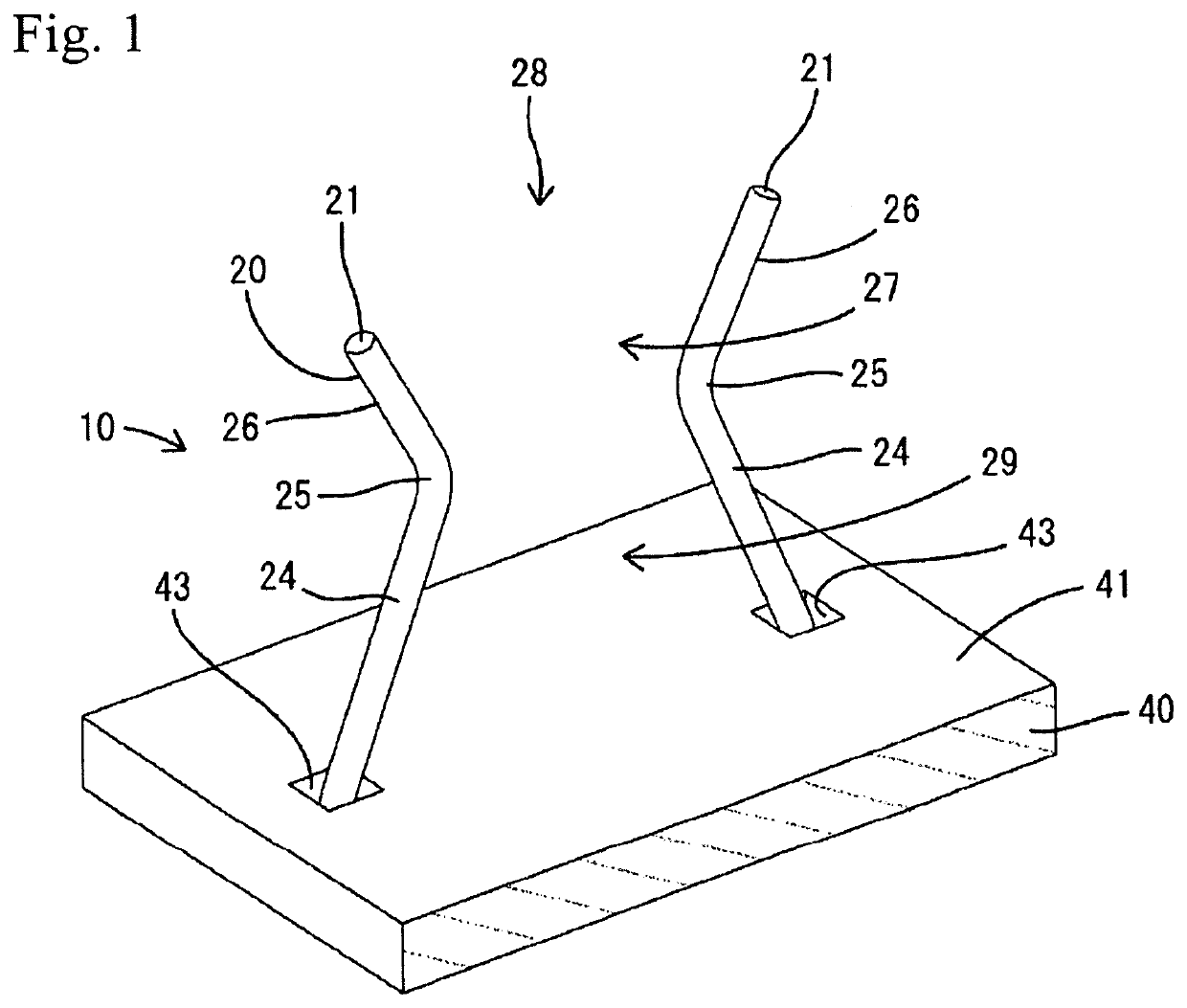
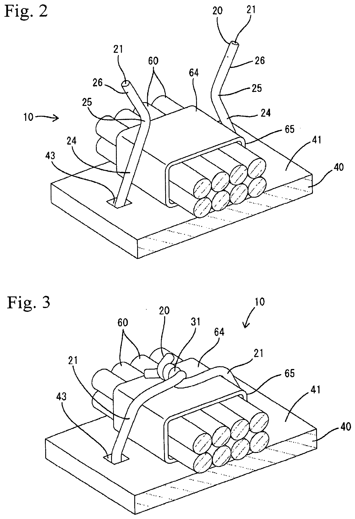
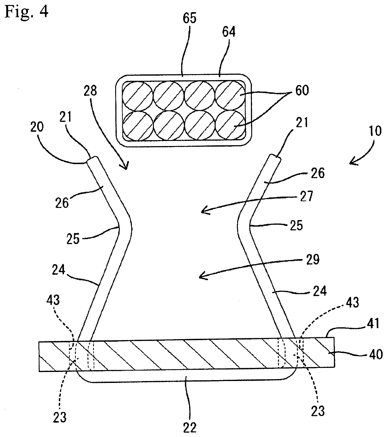
[0022]A first embodiment of a wire unit 10 according to the disclosure is installed in an automatic transmission of an automobile and is used in a portion of control related to transmission operation. The wire unit 10 includes multiple electrical wires 60 configured to connect various electric components such as a ROM and a connector (not shown) to each other, a plate 40 including a support surface 41 that supports the electrical wires 60, and multiple retaining members 20 (only one shown) that retain the electrical wires 60 between the support surface 41 of the plate 40 and the retaining members 20 on a predetermined position in the routing path of the electrical wires 60.

[0023]Each electrical wire 60 is a coated electrical wire having a circular cross section. Although not shown in the drawings, the electrical wire 60 is configured so that multiple core wires are enclosed with an insulation resin. The electrical wires 60 are collected in a bundle and covered with a protection tube...


PUM


Abstract

Provided is a wiring unit that reduces spatial constraints and makes it possible to easily perform wiring work. The wiring unit is provided with: a plate on which a support surface for supporting electrical wires is formed; and a holding member for holding the electrical wires between the support surface and said holding member. The holding member comprises a plurality of holding pieces protruding from the support surface side. After being collapsed from an upright orientation in which the holding pieces stand upright so as to demarcate a guidance space in which the electrical wires are guided toward the support surface side, each of said holding pieces presses the electrical wires toward the support surface side and deforms toward a holding orientation in which the electrical wires are restricted from lifting up from the support surface.

Description

BACKGROUNDField of the Disclosure[0001]This disclosure relates to a wire unit.Related Art[0002]Japanese Laid-Open Patent Publication No. 2014-199069 describes a wire unit installed in an automatic transmission of an automobile. The wire unit includes multiple electrical wires and a retaining plate that includes a support surface supporting the electrical wires. The retaining plate is formed integrally with a pressing portion. The pressing portion includes a side piece projecting from the support surface and a pressing piece that is orthogonally bent from the rising edge of the side piece. The pressing portion is maintained in an L-shaped configuration as a whole. The electrical wires are inserted through a protection tube and inserted from a sideward direction in a press-fitting manner into a gap between the pressing piece and the support surface so that the electrical wires are retained. The electrical wires are fastened to the support plate with cable ties at opposite sides of the...

Claims


Application Information

Patent Timeline
Patent Type & Authority Applications(United States)
IPC IPC(8): H02G3/34F16B9/00
CPCH02G3/34F16B9/05F16L3/06H02G3/32
Inventor KAWASHIMA, YUJI
Owner SUMITOMO WIRING SYST LTD
Learn More